This series is all about installing an advanced software defined network where a controller ensures that our equipment works together. So far we’ve learned what equipment to purchase, how to make network cables, and how to wire our house. Now we need to configure the modem, network edge device, switches, and wireless access points to all work in harmony. This is an exceptionally long post but there is no good place to take a break. Once you start this process you will need to continue until you are completely finished. Warn the family that the Internet is going to be down for a few hours, it’s time to get into it.
In big picture terms we are building a LAN (private network) and bridging it with a WAN (Internet). Your ISP probably set you up with an all-in-one modem, router, firewall, switch, and wireless access point. The first step in our project is to turn off these functions so that they are not interfering with the new network. You are not breaking any rules, most ISPs do not mind if you do this. Many make it easy, or will help you over the phone.
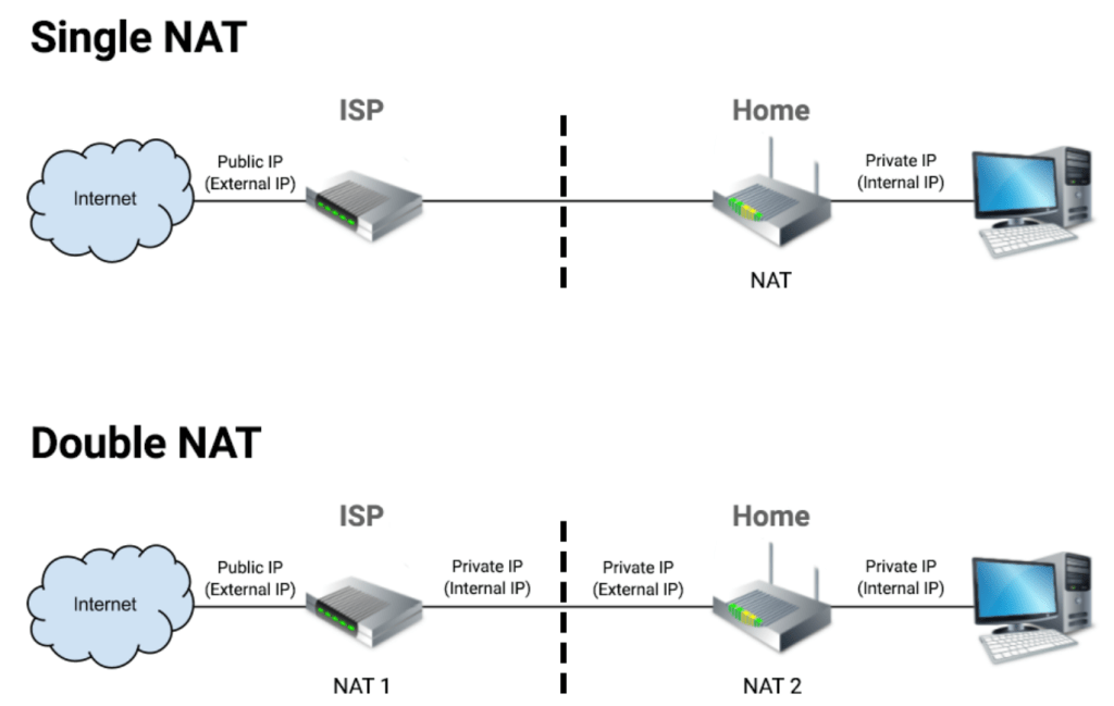
Your ISP’s device (modem) is running network address translation (NAT) to connect all of your stuff through a single public IP address. The details aren’t important, what matters is that having two devices running NAT causes all sorts of problems on networks, especially with real-time communications like gaming, VoIP, and video conferencing. To avoid the double-NAT situation we need to put your ISP device into bridge mode. Instead of behaving like a firewall or gatekeeper your ISP device will pass the Internet public address straight though. Your new edge device will take over the firewall duties.
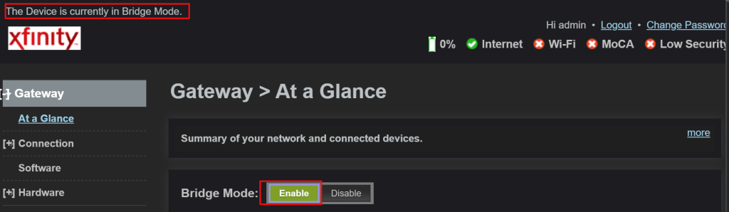
Specific directions for configuring bridge mode aren’t possible, but in general you logon to the admin page and under the settings will be the option for bridge mode. If you can’t find it, locate the model number (usually on the bottom) and Google “How do I put xxxxx in bridge mode”. If that fails, call your ISP and ask them.
While you are in the ISP device’s console find the wireless settings and turn off the radios (usually a drop down). We’ll be using our own wireless access points and don’t want to contend with the signal interference.
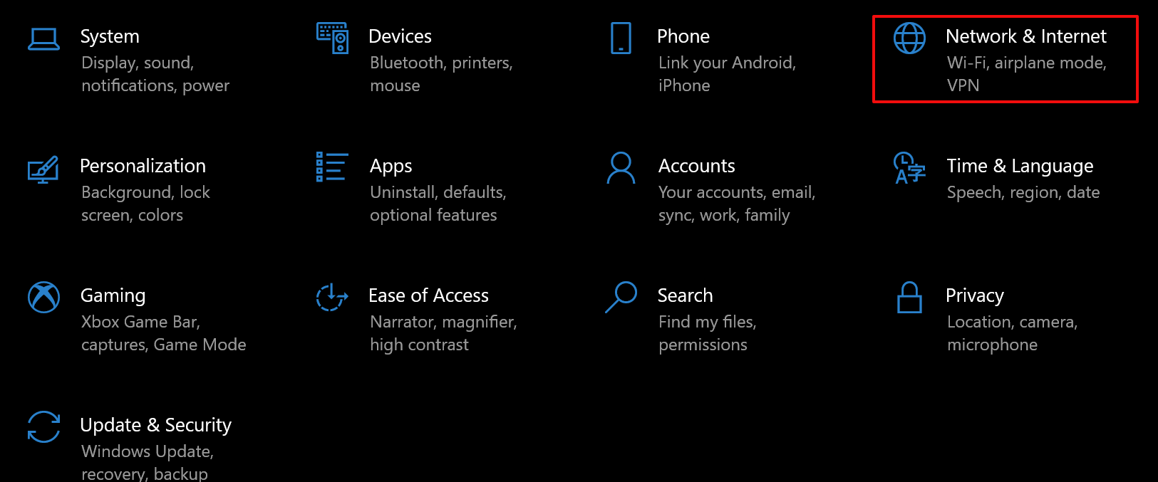
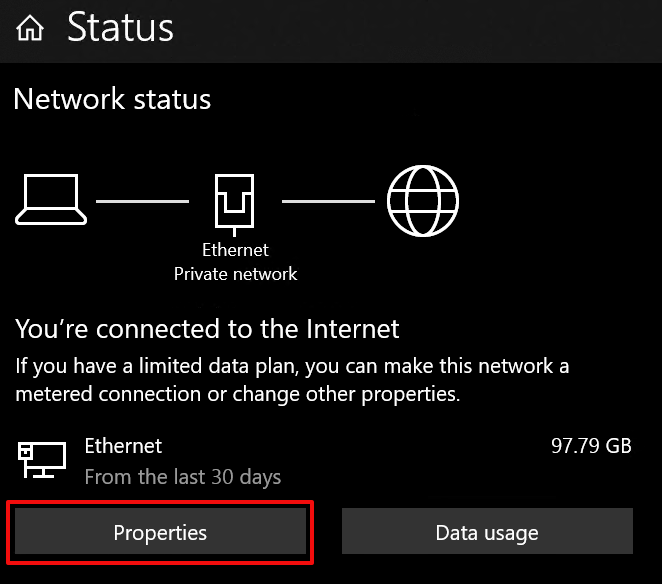
Depending on which software defined network equipment you have we are either ready to install, or configure the controller. If your controller is software that gets installed on a PC, make sure that you set that computer’s IP address to fall inline with your new network.
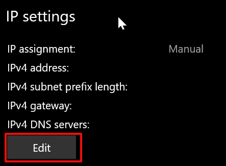
A word on choosing the IP scheme for your new network. Don’t use 192.168.1.0, 192.168.0.0, or 10.0.0.0. These over used private IP ranges cause chaos when you use a VPN to connect to work since many businesses use them too. A full explanation of private IP ranges is TMI, but something like 10.91.14.0 with a subnet of 255.255.255.0 (/24), and a gateway address of 10.91.14.1 would be a good choice. In this case, set the computer that you install the controller software on to 10.91.14.2. If your controller is integrated with your router both services will run on the gateway address (10.91.14.1).
We’ll be using this network (10.91.14.1/24) as an example from here on, but that doesn’t mean that you have to. Try swapping the second and third set of numbers with your birth year and day. The more random your private IP scheme is, the less chance there is for conflict. The first set should be a 10, the next two sets can be whatever you choose between 1 and 254. Each device on your network will get a number (1-254) in the fourth group.
Some edge devices, switches, and access points require that you connect them directly to a computer via a network cable so that you can set their local or LAN IP address. This is done to ensure the controller can locate and program them, a process called adoption. If your devices require this type of pre-adoption configuration they will include instructions on doing so. Read and follow them carefully.
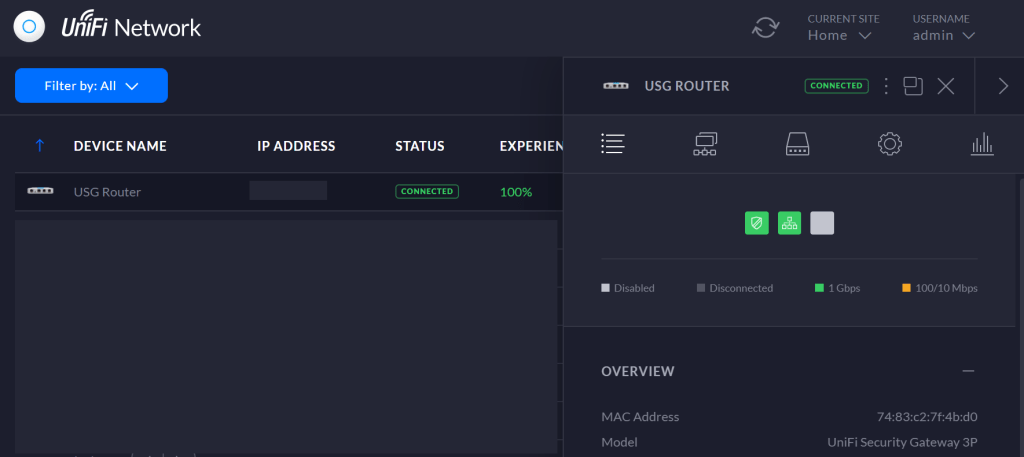
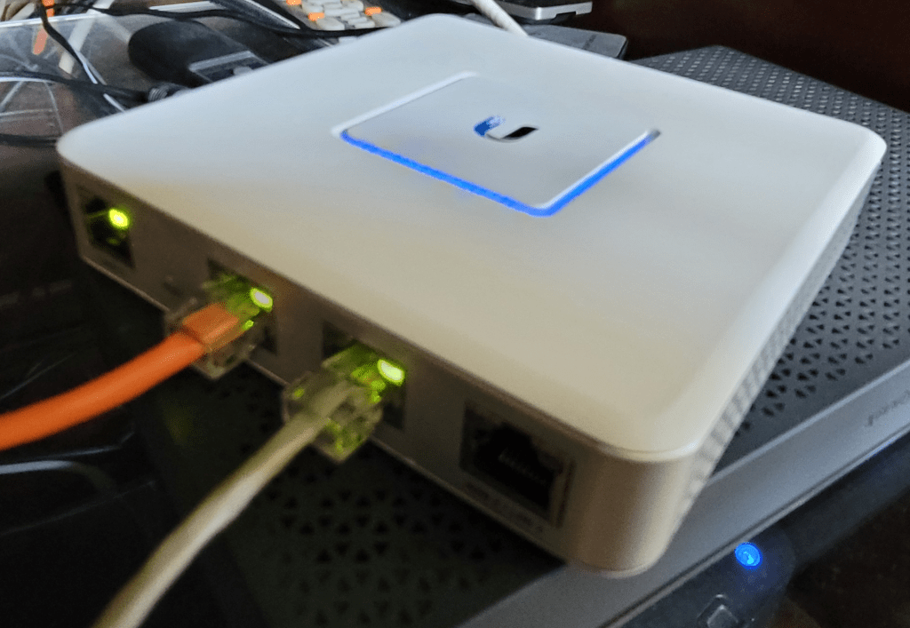
Most Internet connections are automatically configured by the Internet Service Provider. If your modem is in bridge mode and the controller has adopted the edge, you are ready to connect the Internet. Power off your modem and connect a patch cable from its network jack (1 if it has multiple) to the WAN 1 port on your edge device. Some brands label it Internet 1. I like to use a brightly colored patch cable for this connection. Power your modem up and wait for it to complete its boot process. You should see link lights (green blinking) on the modem and edge ports. The status page in your controller should show that you are connected to the Internet.
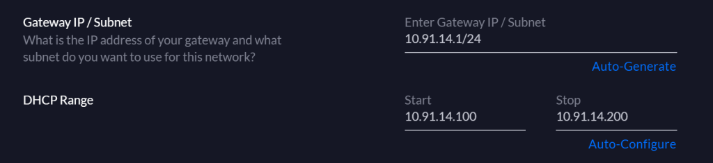
Next we need to define the parameters of our LAN (Private Network). Each of the SDN vendors does this a little differently. Generally you access the console and find the Network tab, button or link (under settings in some). From there, use the fields and options to configure a network that matches what you have done so far. If you assigned your edge device our example address, then your network will be defined as 10.91.14.1/24 or 10.91.14.1 with a subnet of 255.255.255.0 (same network different notation).
If DHCP is not already on, turn it on and configure it. DHCP is a service that configures your devices to work on your network. Its main function is to hand out IP addresses from a pool (range) that you can configure. In our example network 10.91.14.3 – 10.91.14.254 are available for assignment but it is a good idea to exclude some addresses from the pool for those systems that need to be configured by hand (static). I usually configure my pool for the 100 range, 10.91.14.100 – 10.91.14.200.
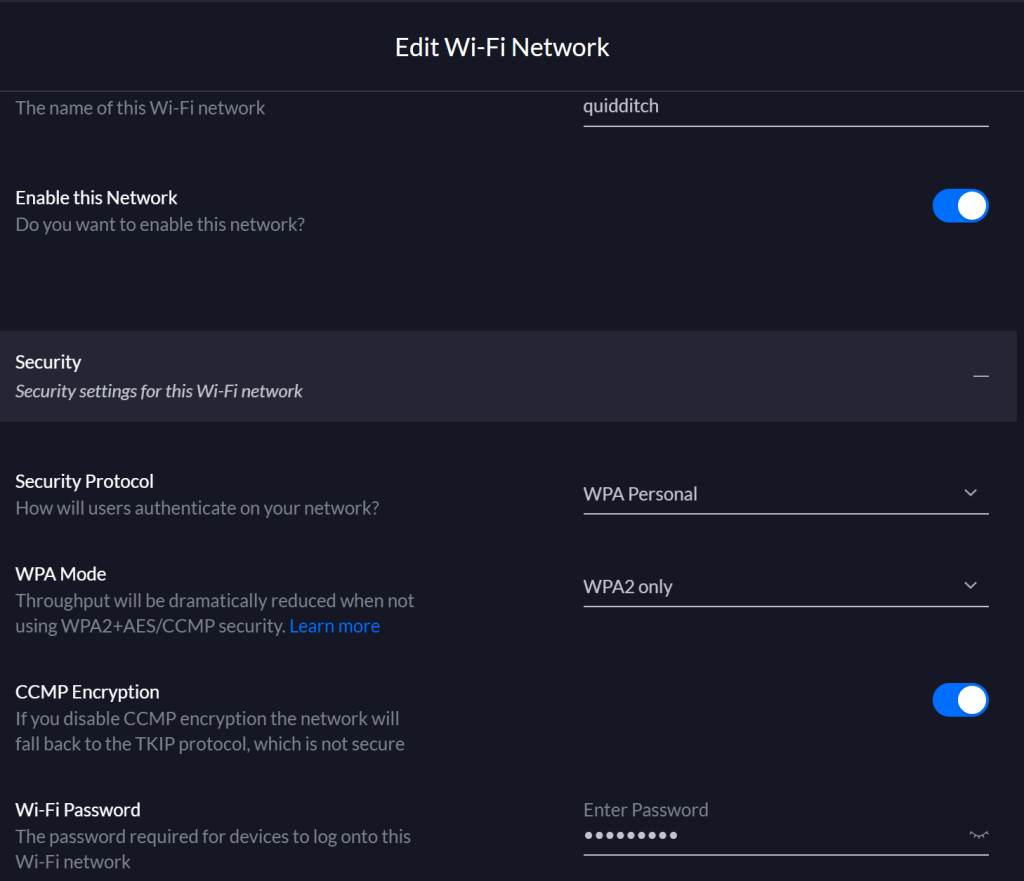
That should take care of the wired side of our network. All that is left is to setup the wireless (Wi-Fi) portion. The beauty of software defined networks is that the controller’s software does all of the heavy lifting, meaning that you don’t really need to know anything about networks. That applies to the Wi-Fi setup as well. You more or less need only to configure the name, security mode (WPA 2 Personal) and password.
Save or apply your controller changes then reboot everything connected to your network. Your modem, edge, switches, access points, computers, tablets, phones, consoles, TVs, everything that uses your network needs to be restated so that it will join up. If they don’t have a power button or reboot option then unplug them from power. Devices that use Wi-Fi will have to be connected to the new one you’ve created. When your other stuff comes back on-line the controller should detect and configure all of the components.
One of the other great features of software defined networks is their reporting. Since everything is controlled from a single point, detailed reporting about usage is a cinch. Enjoy digging into all of the new statistics on your dashboard. Many SDN networks can also be monitored or controlled from an app on your mobile. Check your app store.