
In part 1 of this series we discussed what equipment you would need to purchase to install a modern advanced network in your home. In part 2 we learned how to assemble network cables. Now we’re going to use our new-found skills to install the equipment.
Place a switch and access point on each floor of your home. One needs to be relatively close to your ISP’s modem or jack and an exterior wall. The other switches need to be as close as possible to exterior walls. The plan is to drill small holes using our extra-long 3/8th inch bit through the closest exterior wall of your home so that the cables between each switch can be run on the outside.
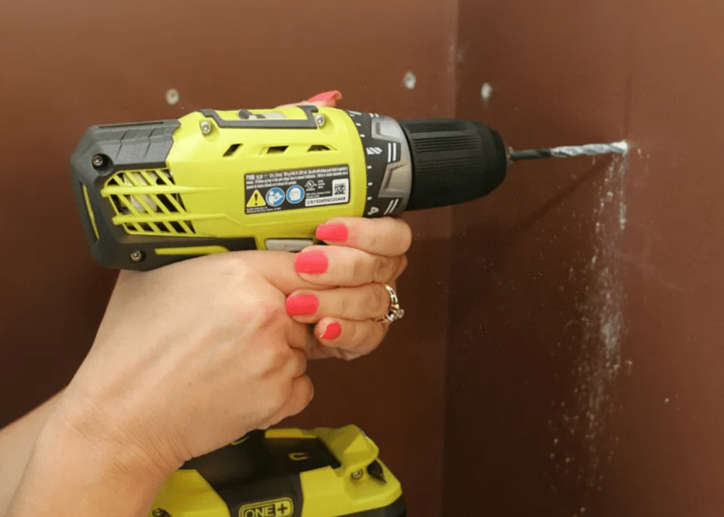
Drill from the inside wall to the outside wall with a 3/8th in extra long bit. 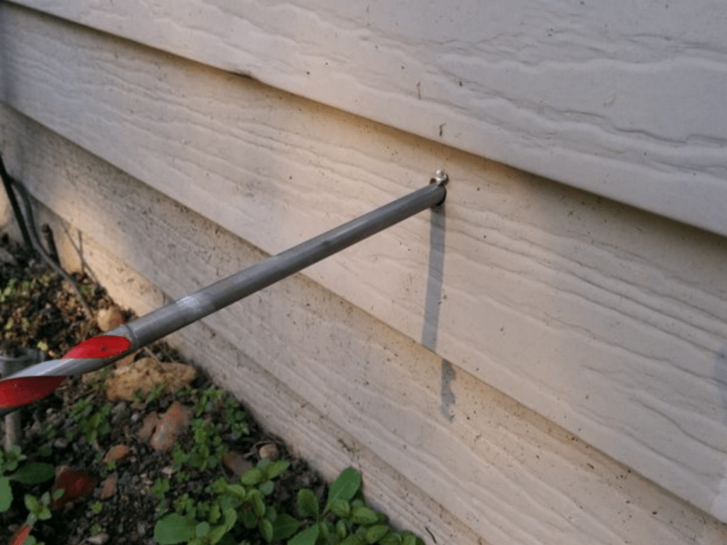
Be careful to avoid unseen components hidden inside the wall.
Think of the switch that is closest to your Internet Service Provider’s modem as the “main” switch and the others as floor extensions. We want to run a cable from each floor extension to the main switch. Your switches should be unboxed and connected to power before beginning.
You are drilling holes at your own risk. You need to be aware of the wall’s composition, drilling through brick or stone is more complicated than drilling through sheet rock and siding. Avoid studs, electric wires, and pipes that may be hidden in your walls. A stud finding device is a good idea.

Once you’ve drilled your first hole, place the box of network cable on the interior side. Thread the cable though the grommet in the box. Get your string and pass it through the eye in your drill bit. If your drill bit doesn’t have an eye, remove the bit from the drill and use a small piece of tape to attach the string to it. Pass the bit and the sting through the hole. If you are using wall plates to hide the cables, you will want to pass the bit and string though it before pulling any cable.
Cut off the end of the string and attach it to your network cable. Some people are able to tie it. I always use tape. Go to the exterior side of the hole and pull your network cable through, using the string.
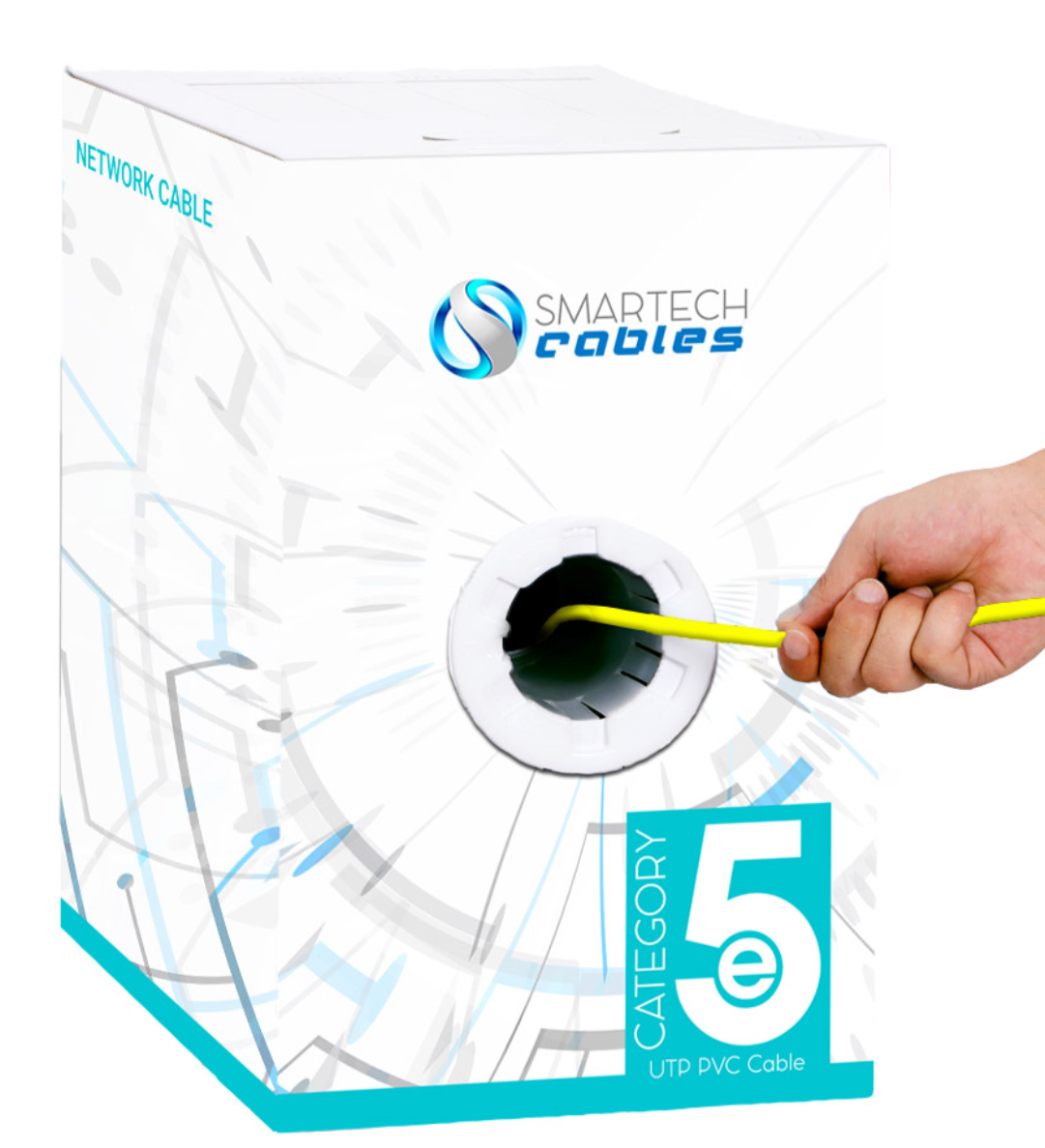
Your box of cable has a built-in dispersal method. 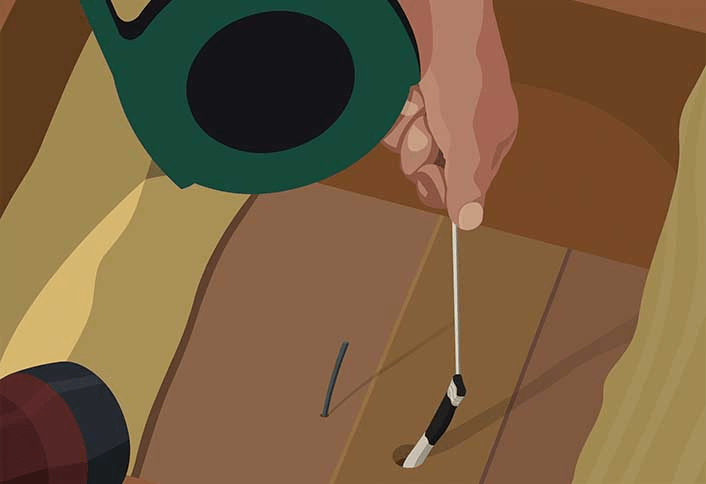
Use string to pull cable though the drilled hole.
Now repeat the drilling process where the main switch is located. If you are running several cables to the main switch make the hole large enough to pass all of them through. Use the same drill bit and string trick to pass the cable you are pulling from the exterior to the interior as close to your main switch as is possible. Always leave a few feet of extra slack in your cable pulls as insurance.
Once you’ve pulled the cables from your floor extension switches to the main switch, use the lessons from article 2 to put RJ-45 ends on them. Plug both ends into switches. You should see the port lights turn on if the connection is good. If you have cable tester, follow its instructions to test your cables before connecting them.
Use the patch cables we made in article 2 to connect one wireless access point to each of your switches. If your WAP can support PoE be sure to connect it to a PoE port on the switch. You should see connection lights as the WAP powers up. Try not to place each WAP directly over the one on the adjacent floor. This will help ensure that strong signals are available through-out your entire home and cut down on any interference.
Use the cable hangers mentioned in the equipment list to attach the outdoor portions of your cables to the exterior surfaces of your home. I try to use the ridges in siding, overhangs, and existing linear features to hide the runs from view whenever possible. When there isn’t an available hide keep the run as straight as possible.
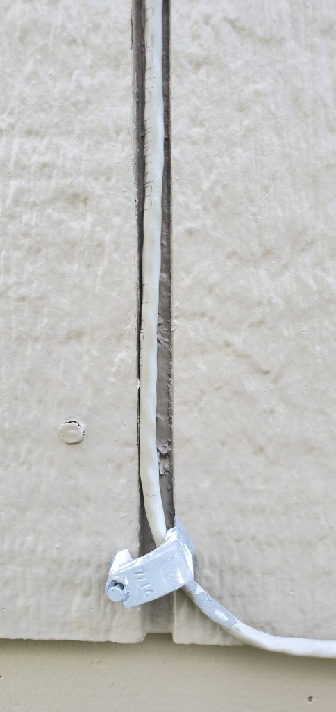
You will want to seal the exit and entry holes with silicone or spray foam. The cable we’ve run is not specifically rated for outdoor use but if it is kept off the ground it will last for years. In the next post in this series we will work to configure your newly installed network and connect it to the Internet.

One thought on “Install an Advanced Home Network – Part 3 Install the Equipment”