Wi-Fi Speed and Wireless Printers: What You Need to Know About 802.11ac Support

What’s not to love about wireless network printers? The flexibility to place them where they are needed, rather than where there’s a network jack nearby, is great. Plop them on a desk or table, plug them in, join the Wi-Fi network and you’re in business.

The majority of wireless network printers on the market today run a type of Wi-Fi known as 802.11n aka Wi-Fi 4. By now, many people and businesses have replaced their gen 4 Wi-Fi router combo or access points with the much faster Wi-Fi 5, or current Wi-Fi 6 gear. Many of us have also upgraded our phones, tablets, televisions, laptops, and consoles to models that run the newer standards.

Wireless GenerationStandardSpeed
Wi-Fi 4802.11nUp to 600 Mbps
Wi-Fi 5802.11acUp to 1300 Mbps
Wi-Fi 6802.11axUp to 7600 Mbps
Each successive generation of wireless technology is more than twice as fast as its predecessor.

It is tempting to dismiss a printer’s network speed as irrelevant. “Who cares if my printer is slow? It’s not like I’m streaming Netflix to it.” If we only needed to consider was how fast your print job or scan finished, this sentiment would be spot on. Here’s the thing, wireless networks have a couple of limitations that many people are unaware of.

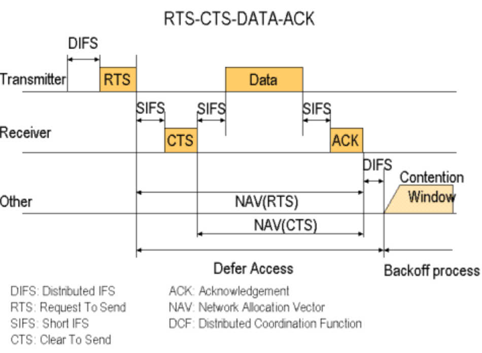
One of the lesser known shortcomings is that wireless networks are half-duplex. The devices connected to them can only transmit or receive data. They can’t do both at the same time like most wired network gear can. The speed data is able to move about on a wireless connection is effectively cut in half right off the bat.

To understand these limitations research 802.11 RTS/CTS. Visualization provided by Stanford University.

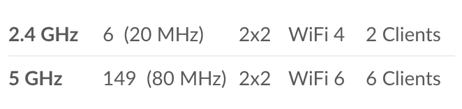
The other little known issue with wireless networking is that a radio generally performs at the speed of its slowest connected device. In our case, the printer. This is true even when the Wi-Fi 4 device is idle (not printing). In other words, if your new Macbook and your printer are connected to the same access point your M2 is stuck in slow lane behind ole’ inky.

There are a few possibilities for workarounds. The first is the easiest. Do you really need a printer anymore? Unplug it and see how life goes. Seriously, not printing is better for your bank account, the planet, and your blood pressure.

If going paperless isn’t an option, ask yourself a simple question, “Does the printer really need to be wireless?” Can you switch to using the printer via USB or a network cable? When considering this question, keep in mind how often you use the printer. Plugging in a USB cable once a month isn’t that inconvenient, but doing it several times a day sure would be.

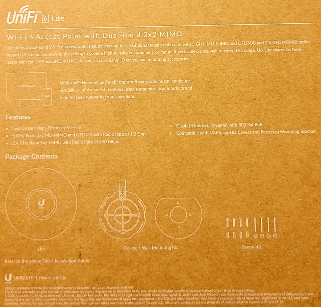
Assuming you need to print wirelessly, there are still a few more options. The least technical of which is to purchase a printer that supports Wi-Fi 5. They can be very difficult to find, but Canon and HP currently offer models that feature 802.11ac. Others are likely to come to market. Check out the Canon Pixma G4270, or the HP Deskjet 2755e.

The only printers that support the 802.11ac standard that I have found so far are linked above. Check the spec sheet for any that you may be considering.

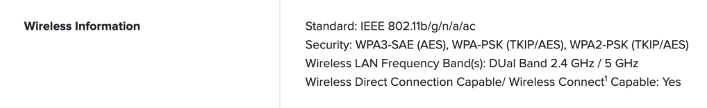
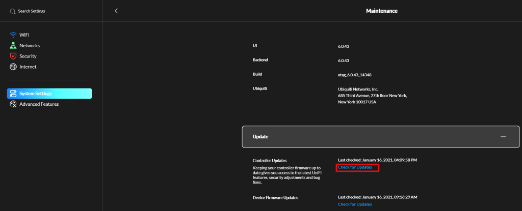
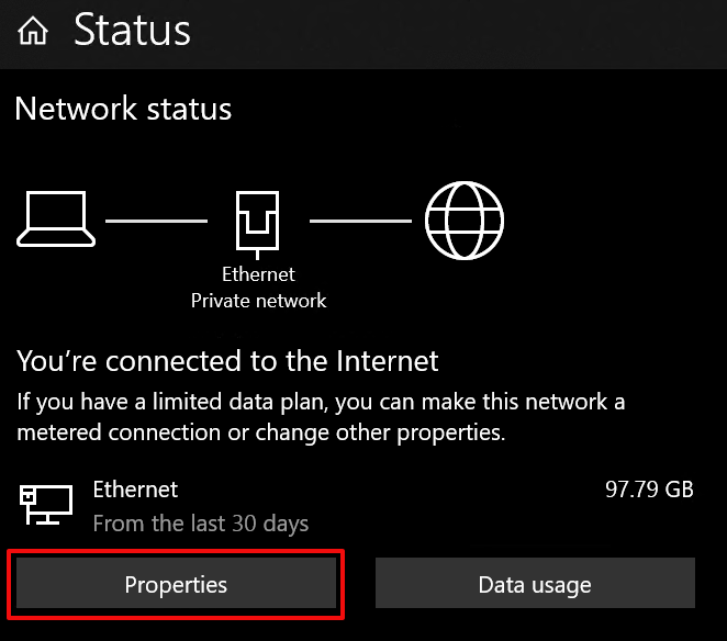
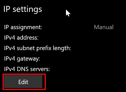
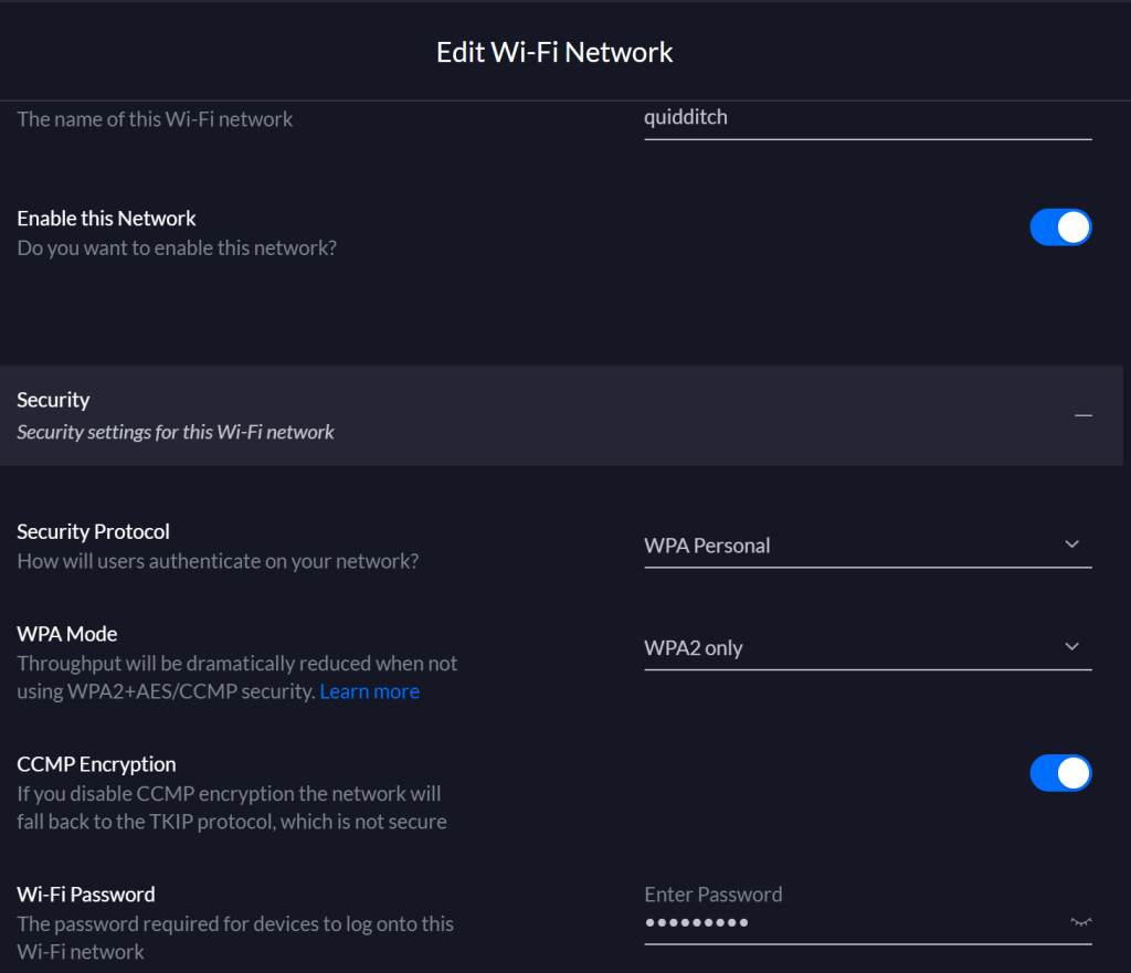
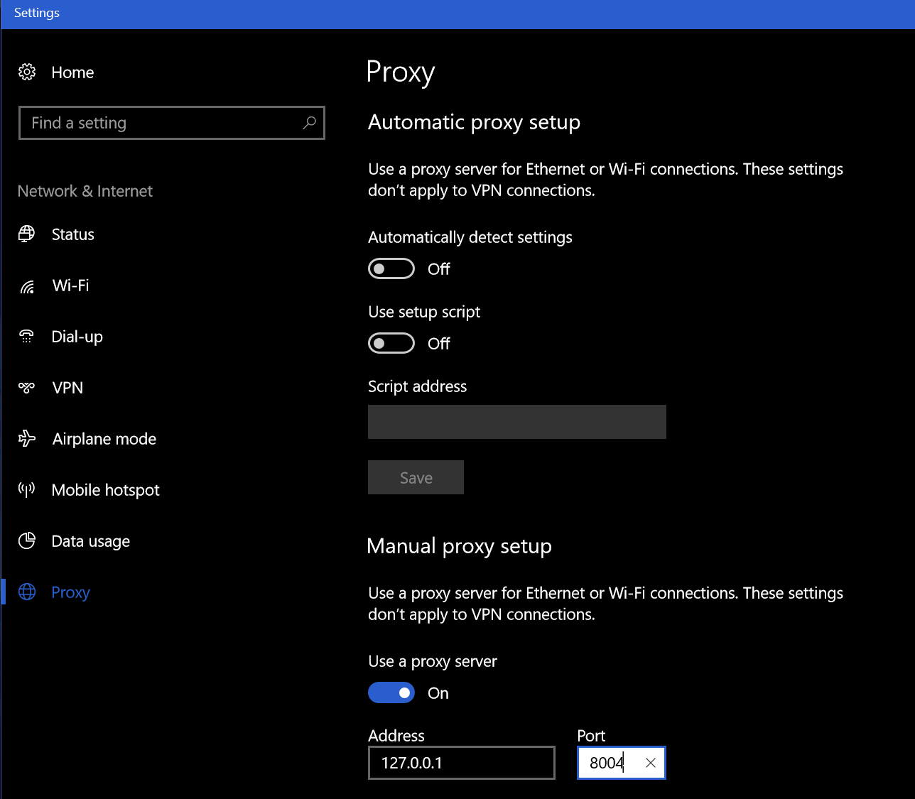
If your current printer does not see or will not connect to your Wi-Fi, the older 802.11 b/g/n is probably disabled. You can enable Wi-Fi 4 on wireless networks because backwards compatibility is a requirement of each new version of the 802.11 standard (to date). Typically turning it on is done by logging on to your Wi-Fi controller/router and accessing the wireless configuration menu. Doing so will introduce the slow down.

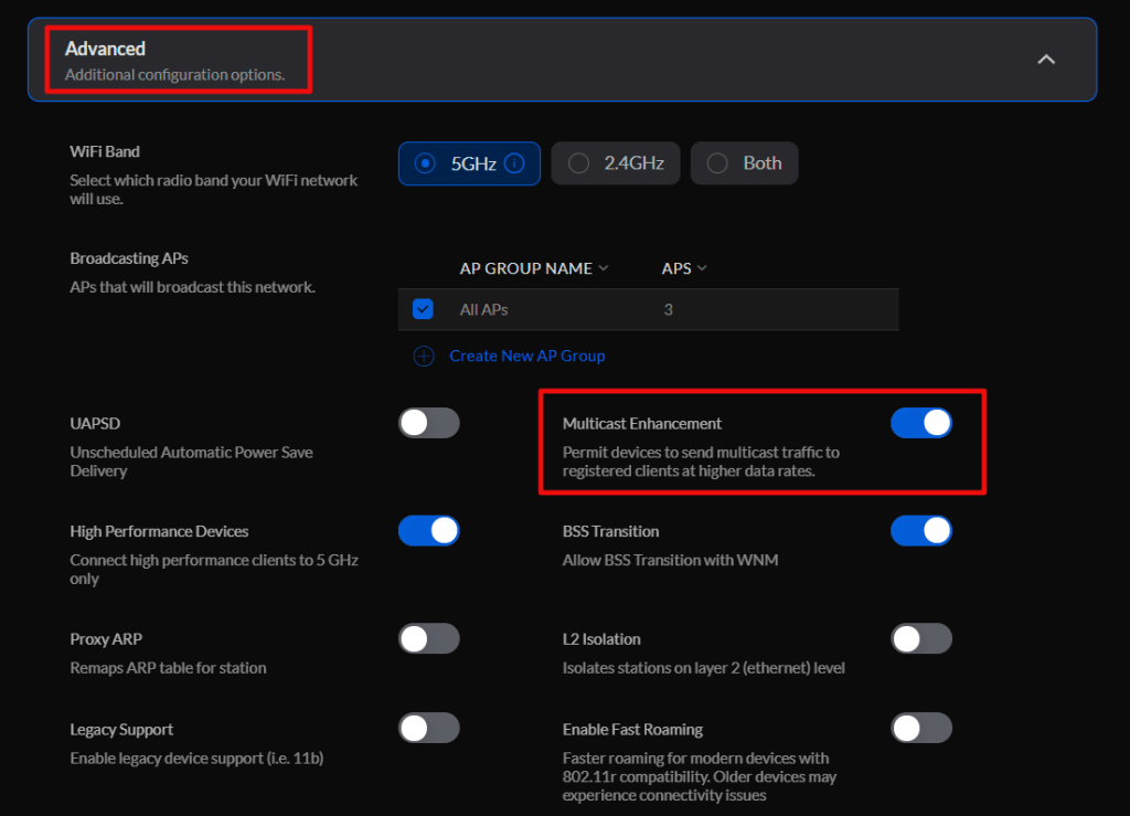
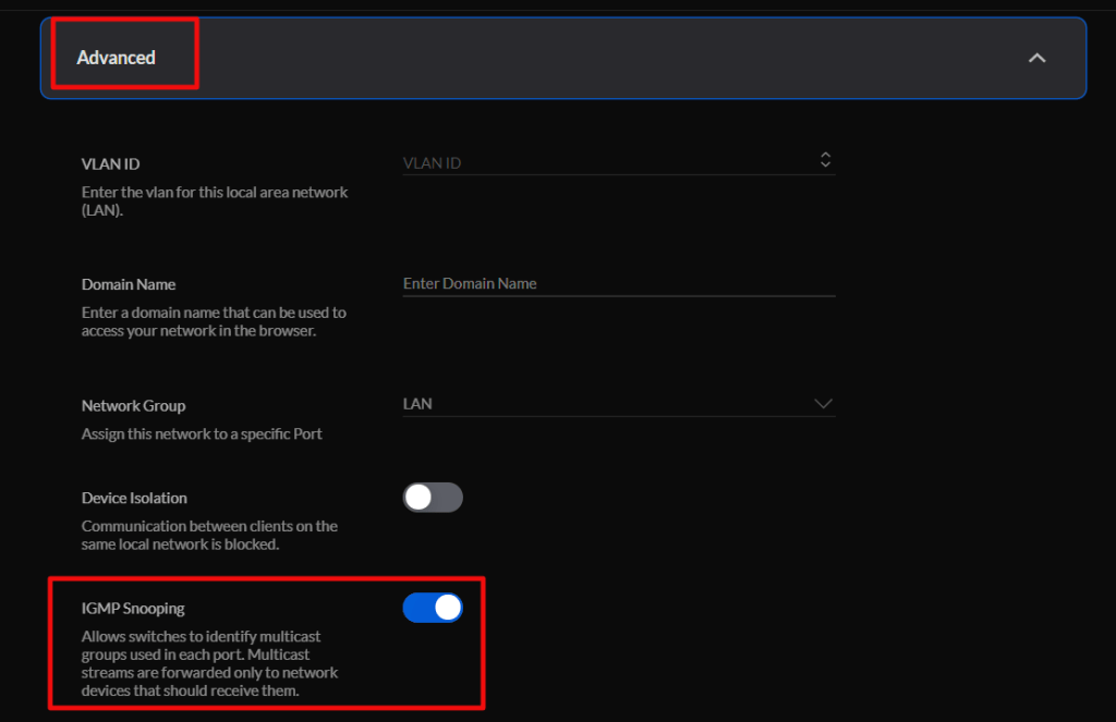
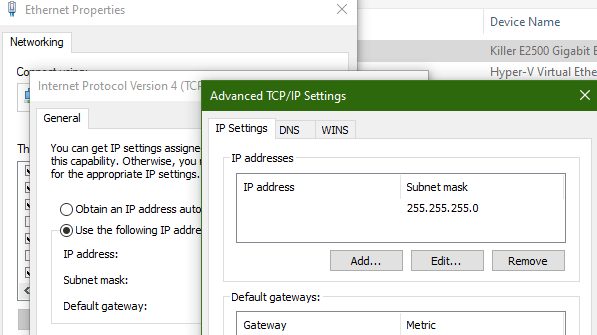
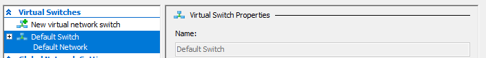
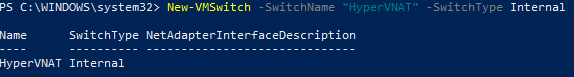
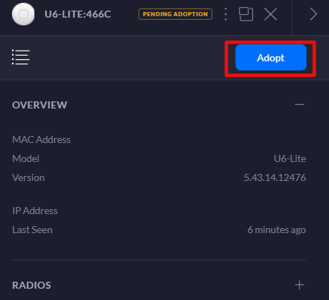
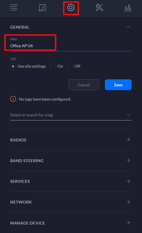
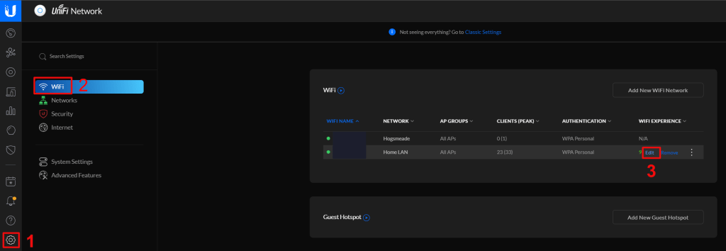
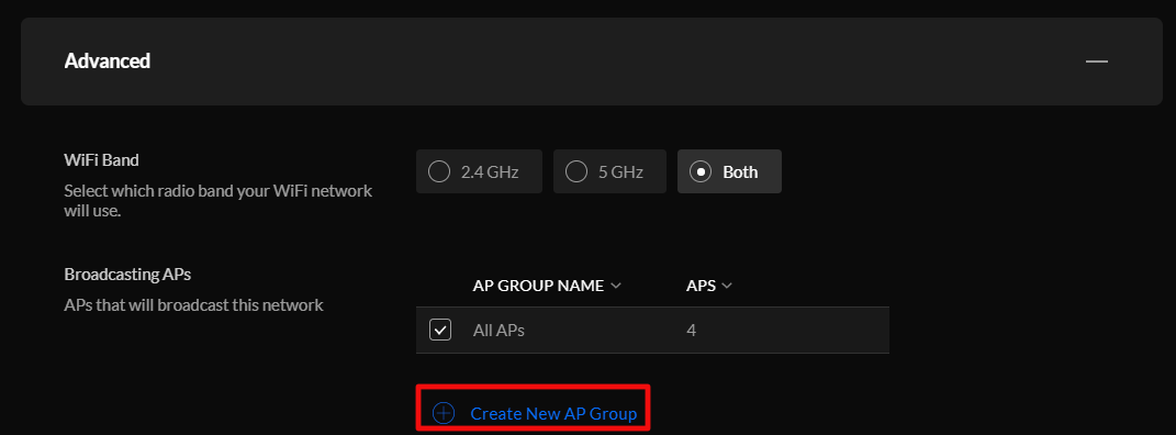
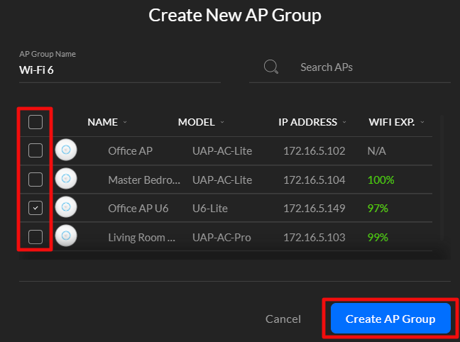
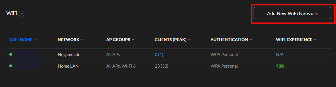
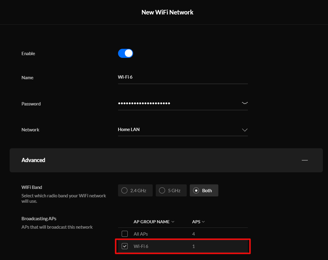
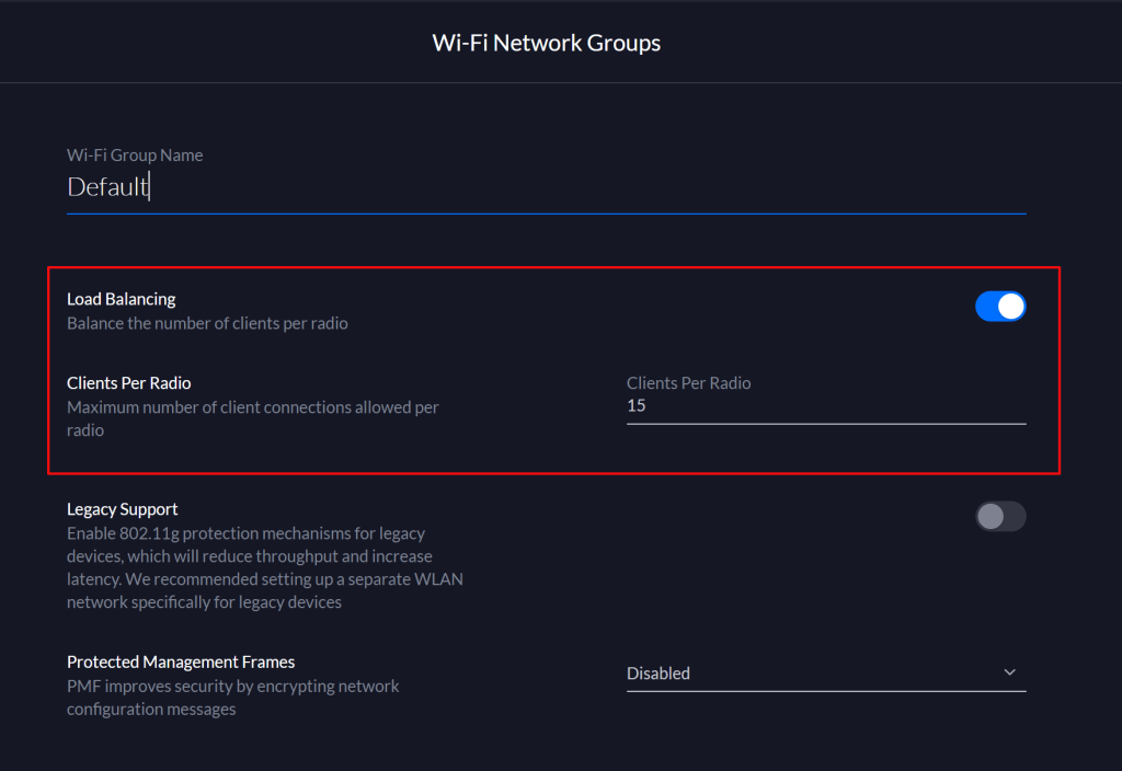
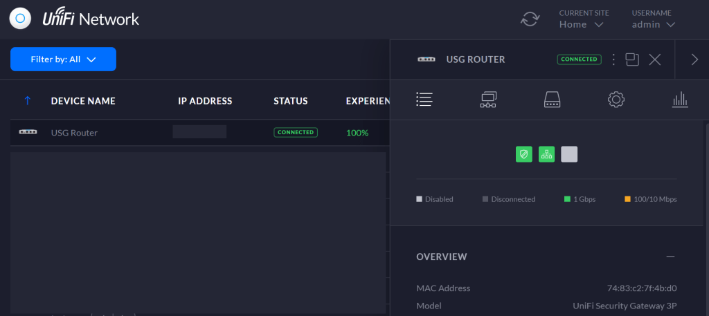
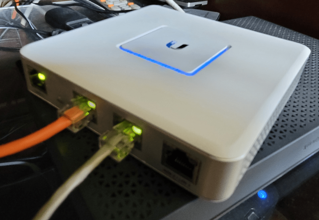
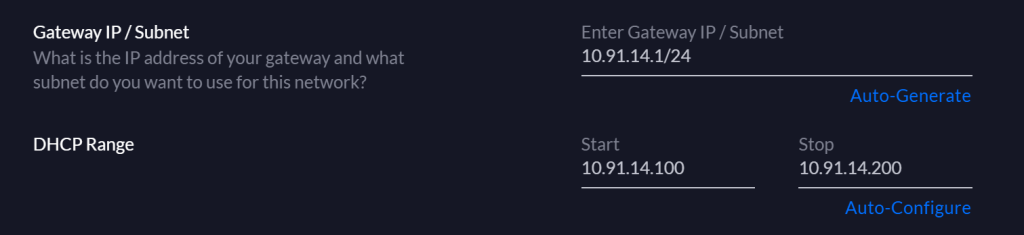
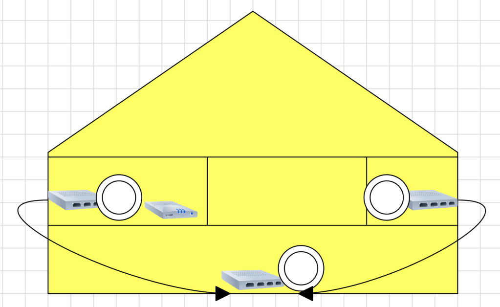
The final option requires network engineering skills. Isolate the printer(s) and other 802.11b/g/n devices to a single radio, access point, or access point group that is configured to run the older standard. Creating an SSID on the same radio you run 802.11ac on is not sufficient, the access point(s) will still run at 802.11n speeds on both SSIDs. VLANs have the same problem unless your AP has multiple radios that you can pin the Wi-Fi 4 network to.

Pinning the older standard to a separate radio is a good strategy. Here’s I’ve forced the Wi-Fi 4 devices onto the 2.4 GHz radio and restricted them from the 5 GHz side of my AP.

Best of luck on your journey to wireless printing happiness.

Fix A Common FortiGate VPN DNS Issue

FortiGates are fantastic UTM devices that are often used as VPN concentrators for remote workers. Their SSL VPN is simple enough to setup but there is a misunderstanding around DNS that I have encountered a few times now.

The problem occurs when an administrator has configured the Fortigate to use internal DNS severs such as Active Directory controllers and those DNS servers have more than one zone. The symptom is that machines connected via VPN can only resolve names from records in the primary AD integrated zone.

Specifically, this happens when the VPN portal is configured to use split DNS. In most firmware versions, split DNS is enabled by default when split tunneling is selected. Administrators often enter the FQDN for the local directory and the IP addresses of the domain controllers, because this is how workstation and server DNS clients work.

It isn’t how split DNS on a FortiGate works. To resolve names in zones other than the active directory integrated zone, you will need to manually enter each additional zone’s domain name. Don’t take my word for it, here is the KB post Technical Tip: Split DNS support for SSL VPN portals.

Oculus Air Link Setup on Unify Networks

Until now, wirelessly streaming games to the Oculus Quest 2 has been limited to using development drivers in combination with specialized software like Virtual Desktop. I’ve written step by step guide to getting that option working here. Now, Facebook has enabled Oculus Air Link which allows streaming of Oculus Store apps too. It was a little tricky to get working on my network so I decided to share what I’ve learned.

Your desktop system must be connected to your network with at least 1Gbps. Your desktop system needs to have at least one USB-C port to connect your Quest with. I’ve heard that a USB-3 port with an adapter works but have not tried it. Your wireless network must support AC or AX (Wi-Fi 5 or Wi-Fi 6) and be capable of sustaining 800 Mbps in the area you intend on playing in. You must have at least WPA2 security enabled on the wireless network. If you don’t meet these requirements you should not proceed.

Assuming your gear all checks out, you’ll need to install the Oculus app on your desktop if you haven’t already. Download it from Setup Your Oculus: Quest, Quest 2, Link, Rift S & Rift | Oculus once you’ve downloaded and installed the software, complete the basic setup by connecting your Quest to your PC via the USB-C cable that came with it and following the wizard.

Your Quest will need to have at least software version 28 installed. In the Quest, go to Settings then About. There’s not much you can do to get the new version if you don’t already have it. Facebook pushes it out slowly like an Android mobile update. You just have to wait for it.

If your network is a mesh topology, the access points can not be wirelessly uplinked. Each one needs to be cabled. Air link is a multicast protocol, your network will need to have Multicast DNS, Multicast IGMP, and IGMP Snooping enabled. These settings are in different places depending on the brand of network gear you are using.

On Unify networks, enable Multicast Enhancement in the advanced settings for the WLAN you will connect your headset to.

Enable IGMP Snooping in the advanced settings for the network your WLAN is connected to.

Finally, turn on Multicast DNS in the Advanced Gateway settings under the Advanced Features menu.

The PC running the Oculus desktop software can not have more than one IP address assigned to the network adapter that is on the same network as the Quest. This causes the Launch button to be greyed out, the Quest will pair but multicast will not function properly. Check the advanced IP settings for your network card and ensure that only one address is listed there.

Now enable the Air Link option in the Oculus desktop software under Settings -> Beta.

All that is left is to put on your headset and go to the Settings menu. Then go to Experimental Features and turn on the slider for Air Link. Now go to the Quick Action menu in Settings and select the Air Link button at the far right. The first time you run Air Link you will need to pair your headset with your computer. Then tap the Launch button. After a few moments the Oculus Desktop Home should load and work just like it does from a link cable or Rift.

Hyper-V NAT: Remote Access to Windows and Linux Virtual Machines

I’ve written several posts on creating Hyper-V virtual machines on Windows 10. One of my most popular covers how to create a Linux VM with sound. Inevitably, somebody will follow up with a question along the lines of, “How do I access XRDP (Linux RDP Server) from other machines on my network?”

One might be tempted to think the answer to this question is just a simple firewall rule. It isn’t. After the Windows 10 1607 update, Hyper-V started including a default virtual switch that uses NAT to allow your virtual machines access to the same network resources that your host machine can reach. This default switch makes the Quick Create function extremely useful. With a couple of button clicks, you can deploy a VM that has full outbound (Internet) network access. No network chops required.

Your newly deployed VM will be running on its own network segment that uses NAT to reach the host network’s resources. It is fantastic when you are trying to go from your VM out to the world. Getting traffic to go in from your host network(s) to your VM is another matter. Since the VM is running in its own network, there’s no path for traffic to reach it. The NAT is handled on your Windows host system so your router won’t be much help either.

Like all technical problems there are multiple ways to address this challenge. For example, if all the machines you intend to access the VM from are running Windows 10 Pro +, or Windows Server 2012 + you could configure the Hyper-V manager to access the host remotely. I’ve written those instructions here. You could also create an external virtual switch that would allow your VMs to use the same network your host system is attached to. In this post I’ll create a new NAT virtual switch and forward the traffic to the VMs.

Windows 10 has built-in port forwarding and NAT mapping. Normally you would need a few lines of PowerShell to forward the packets to your VM, but there’s a problem. The Hyper-V default switch’s NAT is not exposed to the OS. If you open PowerShell and run Get-NetNat you will probably see no return (assuming you haven’t configured other NAT mappings). We need to create a virtual switch that uses NAT and allows us to control it. Microsoft has not included this functionality in the GUI, but it can be done.

First we need to create a new Hyper-V switch. In an elevated PowerShell console run:

New-VMSwitch –SwitchName “HyperVNAT” –SwitchType Internal

If you look in the Windows network adapter console, or list them with PowerShell (Get-NetAdapter), you will see that a new NIC has been created with the name you specified between the “” marks in the command above. It can’t access anything because it isn’t configured. First we need to give the switch adapter an IP address. This address will be the gateway for all the VMs that are attached to this virtual switch.

New-NetIPAddress –IPAddress 172.16.41.1 -PrefixLength 24 -InterfaceAlias "vEthernet (HyperVNAT)"

Now we need to create a NAT rule for our new network:

New-NetNat –Name HyperVNATNetwork –InternalIPInterfaceAddressPrefix 172.16.41.0/24

The built-in default virtual switch includes a DHCP function that automatically assigns IP addresses to the attached VMs. Our new virtual switch does not. You will need to manually assign your VM an IP address in the same subnet. If you followed my example, the useable addresses are 172.16.41.2 – 172.16.41.254 the subnet is 255.255.255.0, and the gateway is 172.16.41.1. You’ll also need to configure DNS if you plan on surfing the web or accessing named resources, 8.8.8.8 is Google’s public DNS server.

There are numerous ways to configure the IP information for a computer. They all differ according to the operating system. Generally, somewhere in the settings of your OS should be the network options. Set the IPv4 interface to manual (not automatic or DHCP) and enter the correct numbers for each. Below I’ve configured an Ubuntu Linux machine for the network we’re creating in this post.

It is always a good idea to reboot after changing an IP address.

Now the VM should be able to use our new virtual switch to access the outside world. Also, when we run Get-NetNat on the host in PowerShell you’ll see information returned. You should be able to open a web browser on your VM and hit your favorite sites or check your email. We’ve done all of this and basically ended up where we started LOL. The key difference is that the NAT rules can be controlled now.

The problem we started out to solve was to allow XRDP access to a Linux VM on our Windows 10 host from other computers on our network. Add a NAT mapping to forward a custom port (3391) from our host to our VM as XRDP (3389) by using the PowerShell command below. Note: Do not forward 3389 to 3389 unless you do not use RDP on your host system.

Add-NetNatStaticMapping -NatName "HyperVNATNetwork" -Protocol TCP -ExternalIPAddress 0.0.0.0/24 -ExternalPort 3391 -InternalIPAddress 172.16.41.11 -InternalPort 3389

If your Windows Firewall is enabled (should be) you’ll need to create a rule to allow the forwarding port, 3391.

New-NetFirewallRule -DisplayName "HyperVRDPNat" -Direction Inbound -LocalPort 3391 -Protocol TCP -Action Allow

Depending on how XRDP was installed and configured on your Linux machine, you may also have to edit the XRDP.INI file. If XRDP is configured for vsock, it is not listening on the traditional RDP port. Vsock is only accessible via the Hyper-V management console’s enhanced session function.

sudo gedit /etc/xrdp/xrdp.ini

Depending on the distro, you may need to use nano or vim to make sudo changes to the xrdp.ini file. Change the line use_vsock=true to use_vsock=false. Make sure there is a port=3389 line that is not commented out (;) and save the file. Reboot the VM.

Note: chaining this setting will mean that to connect to an enhanced session, you will always need to manually open an RDP connection. Right clicking on the VM in the Hyper-V Management console and choosing connect will only open a basic session if vsock is disabled.

You should now be able to connect to RDP via the Windows 10 host’s IP (not the VM’s) address to port 3391 (X.X.X.X:3391) from any machine that is able to reach your Windows 10 host computer. If you want to access the VM from the Internet you would need to forward the custom port (3391) from your external firewall to your Windows 10 host system.

This technique was demonstrated in Windows 10, but it would work for Windows Server and a Windows Docker Container as well. You can find more details about the NAT abilities built into Windows at Set up a NAT network | Microsoft Docs .

Accidental MFA Bypass in Fortinet Devices

Due to a misunderstanding of a poorly designed form it is easy to allow LDAP to bypass Fortitokens or other MFA technologies when implemented on Fortigate VPNs. In a Fortigate VPN configuration, you create an inbound rule to allow VPN tunnel access. That rule specifies the source objects and groups that have access to the tunnel.

Typical Fortigate Inbound Rule

In the example above you see that a firewall group named SSLVPN-GROUP is allowed to use the tunnel. The bypass arises because the form that controls that group does not make it clear that adding an object to the remote groups section is an additional accepted authentication source.

I assume that some engineers are interpreting the remote groups section as a directory lookup for users placed into the members section of the firewall group. The bypass occurs due to Linux and Window’s interpretation of character case. If the user enters their credentials in a case that matches the way it appears in the member’s section of the firewall group, they will be prompted for their MFA token.

However, if the user enters their credentials in the client using a case that is different (all caps, mixed case, etc.) then the credentials will not match a member of the group. The Firewall group will then proceed to check the remote groups, in our example this would be an LDAP server. The credentials will match (Windows doesn’t consider case in usernames) and the user will be logged in without MFA.

LDAP directory lookups are accomplished by selecting the protocol and then the LDAP server object when adding new users to the Firewall group, not by including it as a Remote Group.

If you have Fortigate VPN devices in your environment, I suggest that you ask your network engineer to check for this situation. I’ve run into the misconfiguration quite a few times in the field. I’ve submitted a feature request to Fortigate to have the “Remote Groups” section on the form more clearly defined.

PowerShell: Automate UniFi Controller Software Updates on Windows

The Windows software based controller for your UniFi wireless network is more useful when run as a Windows service. Running the controller as a service allows it to start automatically when your computer reboots, among other things. If you haven’t already configured it to run as a service, see these instructions on the UniFi support site UniFi – Run the Controller as a Windows Service – Ubiquiti Support and Help Center.

The downside of running the controller software as a service is that updates become considerably more painful to accomplish. You have to uninstall the service, install the update, and then re-install the service by issuing a series of commands each time. It isn’t difficult. just annoying.

I wrote the script below to automate most of the process. Copy the code and paste it into notepad. Save the file as Update-UnifiControllerService.PS1 in your documents folder, or wherever makes sense to you. The next time your controller console prompts to download a software update, do so. Then open an elevated PowerShell console (as administrator) and run the script by typing .\Update-UnifiControllerService.ps1 then press Enter.

# Author: Techbloggingfool, https://techbloggingfool.com
# Update-UnifiControllerService.ps1
# This script assumes that you have already configured the UniFi controller to run as a service and are upgrading it with a new version that you have already downloaded to your hard drive or another location Windows Explorer can reach.
# Directions to configure the Windows Unifi Controller to run as a Windows service the first time can be found here: https://help.ui.com/hc/en-us/articles/205144550-UniFi-Run-the-controller-as-a-Windows-service

Write-Host "Uncheck the box to start the Unifi Controller at the end of its installation!"
Write-Host "Make a backup of your controller before upgrading. The script will pause."
Pause

#Stop the Unifi Service
Stop-Service -Name UniFi

#Loading VisualBasic interactions to create GUI
[System.Reflection.Assembly]::LoadWithPartialName('Microsoft.VisualBasic') | Out-Null


Function Get-FileName($initialDirectory)
{   
 [System.Reflection.Assembly]::LoadWithPartialName("System.windows.forms") |
 Out-Null

 $OpenFileDialog = New-Object System.Windows.Forms.OpenFileDialog
 $OpenFileDialog.initialDirectory = $initialDirectory
 $OpenFileDialog.filter = "EXE files (*.exe)| *.exe"
 $OpenFileDialog.ShowDialog() | Out-Null
 $OpenFileDialog.filename
} #end function Get-FileName

#Use the Get-FileName function to find the UniFi Controller Upgrade file
$controller_exe = Get-FileName -initialDirectory $env.userprofile\downloads

#change to the unifi user directory
cd $env:userprofile
cd 'Ubiquiti Unifi'

#execute the java command to remove the existing service
java -jar lib\ace.jar uninstallsvc

# install the upgrade
Write-Host "Please complete the Unifi Installation. Uncheck the box to start the Unifi Controller at the end"
& $controller_exe
Pause

#execute the java command to create the windows service
java -jar lib\ace.jar installsvc

#start the new service
Start-Service -Name UniFi
Get-Service -Name UniFi
Pause
Exit

You will need to run PowerShell as an administrator to start and stop the services.

Right-click on the Start button and pick Windows PowerShell (Admin) from the menu. CD\ to the folder you saved the script in.

The script will pause and ask you to make a backup of your controller.

Logon to the UniFi web interface and click the gear icon at the bottom left to go to settings. Click System Settings in the menu and then expand Backup / Restore. Click the Download Backup link and save the file to your PC.

Always a good idea to backup your controller before you upgrade it.

Return to the script (click it on your task bar) and press enter to continue. The script will stop the running UniFi service and open an explorer window. Locate the downloaded update file and click the Open button.

Locate the update file and click Open.

The update installer does not have command line options so you will need to use its GUI to complete the installation. The script will pause and open the installer. Click the Install button.

Click Yes when asked if you want to upgrade.

Click the Yes button when asked if you have made a backup.

Uncheck the box to start the controller and click the Finish button.

Now return to the script (click it on your task bar) and press Enter to continue. The service will be installed and started. The script will pause one more time to show you that the service is running. When you press Enter, you are done. The upgrade has been completed, close the PowerShell window. Anytime an update is available, download it and repeat the process.

Add Wi-Fi 6 to your UniFi Network

The sixth generation of wireless networking, technically named 802.11ax, has been available for around a year. However, mainstream devices are just now starting to take advantage of the upgraded capabilities. Wi-Fi 6 access points can be difficult to obtain, I was able to order one for my UniFi system straight from the manufacturer’s online store. Amazon, BestBuy, and other vendors were continually sold out.

Before we get into the particulars of how to install the equipment, a word on why you might want to. Fifth generation wireless networks also known as 802.11ac have a maximum speed of 866 megabits per second. 802.11ax devices can reach 1200 megabits per second. In my case, I stream Steam VR games from my PC to my Oculus Quest 2 and the extra bandwidth will let me crank the graphics to their max.

UniFi 6 Lite Packaging

I ordered the Unifi 6 Lite access point and am blogging the experience of adding the unit to my network as I do it in real-time. My entire network is based on the UniFi system; the controller, router, switches, and access points. If your topology incorporates another vendor’s products your experience may be different. The 6 Lite unit does not include a PoE injector, if your network switch does not support power over ethernet you will need to purchase a separate adapter.

Anytime I start a project like this the first thing I do is make sure that all the software is up to date. At the time of this writing 6.0.43 is the newest edition of the Windows UniFi Controller software. Go to System Settings -> Maintenance -> Update and use the link to check for updates.

Update your UniFi Controller Software before installing the new WAP.

Unbox the unit and connect it to a PoE switch port using a suitable RJ-45 connection. Logon to your UniFi controller. The WAP should power on as indicated by the ring light on top flashing, then the unit will be detected by the controller, look in the devices section to locate it. Click on the device and then select Adopt in its pop-out panel. This process can take several minutes so be patient.

Before adding the new WAP to any of your AP Groups or creating one just for it, you’ll want to upgrade the firmware. While still in the Devices section of the controller, hover your mouse over the newly adopted access point and a menu will appear at the far left. Press the upgrade button and then click Confirm. Again, the process can take several minutes.

Upgrade the WAP firmware.

While still in the Devices section of the controller, click on the device after its firmware upgrade has completed to access its pop-out panel. Click the settings (gear) icon and name the device something appropriate for your network. You can also adjust any other settings that may be required for your environment in this panel. Save and Apply the changes.

Name your Wireless Access Point so that you can easily locate it in the controller and to make logs / events easier to understand.

In my case, I am adding the UniFi 6 unit into the same AP group as the rest of my access points and will let the controller decide what clients should connect to it. So, my project is complete at this point. You could also create a separate AP group for the new WAP and add it to a stand-alone WLAN (Wireless LAN / SSID) to enable manual selection of the Wi-Fi 6 network. While logged on to the controller click the settings (gear) icon in the menu on the left. Then go to Wi-Fi. Hover your mouse over your WLAN (SSID) and click the Edit button when it appears.

Edit WLAN settings to access the AP Group function

Use the Advanced menu to access the AP Groups. To isolate your Wi-Fi 6 unit into its own SSID you will need to create two new groups. Click the New Group button and select the devices that compose your current SSID, leaving the new unit unselect. Name this new group something appropriate (suggest same as SSID) and the click the create group button. Now create another group that contains only your Wi-Fi 6 WAP and name it. Select the first group you created to bind it to your current SSID. Save and apply the changes.

Now create a new WLAN from the Wi-Fi settings screen and choose the Wi-Fi 6 AP group after you have configured all the SSID settings. Devices that you manually join to this new SSID will be connected to Wi-Fi 6 access point. If you add new Wi-Fi 6 access points you can add them to this group using the same method.

Once you have provisioned your Wi-Fi 6 access point and bound it to a wireless network connect a device to it and prepare to be astonished. On Windows systems and notification pops up to inform you that you’re using a more advanced network. On Android devices a little number 6 appears next to the wireless connection symbol. Checking the properties of the connection should show that you have 1.2 Gb/s of bandwidth available.

Fixed Frequent UniFi Wireless Disconnects

My network is based on Ubiquiti’s Unifi platform. I’m on my second generation of the equipment and have been very satisfied with it overall. Normally it just does its job and disappears into the background. So you can imagine my frustration when multiple devices started randomly flapping. My Oculus Quest would disconnect and reconnect mid-game. My wife’s iPad and kids laptops did the same.

Nailing down the cause was troublesome. I couldn’t find a pattern or common denominator to drill in on. No changes coincided with the onset and all the software and firmware were up to date. The event logs on the controller and devices recorded the disconnects but didn’t show a reason.

I spent a few hours working through Ubiquiti’s excellent support material. Specifically this document https://help.ui.com/hc/en-us/articles/221029967-UniFi-Troubleshooting-Connectivity-Issues#intermitten. Unfortunately, it didn’t directly lead to a resolution.

I had installed Wireshark as part of the troubleshooting process and left a capture running while I used my laptop. Eventually the issue occurred and I was able to see in the trace that the RESET packet was coming from the AP that I was connected to. It was intentionally disconnecting my client. Thinking about this logically jogged my memory.

The UniFi system has a load balancing feature that can be used to control the number of clients connected to each access point. I checked and mine was set to five devices. I have more than thirty connected devices at any given time and three radios. The system was disconnecting and attempting to move clients too frequently trying to satisfy the load balancing setting. I bumped the limit up to fifteen devices and haven’t had the problem since. Not only that, but my wireless devices are actually being balanced across the available radios again.

Clients per radio should be a quotient of active devices.

Install an Advanced Home Network – Part 4 Network Configuration

This series is all about installing an advanced software defined network where a controller ensures that our equipment works together. So far we’ve learned what equipment to purchase, how to make network cables, and how to wire our house. Now we need to configure the modem, network edge device, switches, and wireless access points to all work in harmony. This is an exceptionally long post but there is no good place to take a break. Once you start this process you will need to continue until you are completely finished. Warn the family that the Internet is going to be down for a few hours, it’s time to get into it.

In big picture terms we are building a LAN (private network) and bridging it with a WAN (Internet). Your ISP probably set you up with an all-in-one modem, router, firewall, switch, and wireless access point. The first step in our project is to turn off these functions so that they are not interfering with the new network.  You are not breaking any rules, most ISPs do not mind if you do this. Many make it easy, or will help you over the phone.

Your ISP’s device (modem) is running network address translation (NAT) to connect all of your stuff through a single public IP address. The details aren’t important, what matters is that having two devices running NAT causes all sorts of problems on networks, especially with real-time communications like gaming, VoIP, and video conferencing. To avoid the double-NAT situation we need to put your ISP device into bridge mode. Instead of behaving like a firewall or gatekeeper your ISP device will pass the Internet public address straight though. Your new edge device will take over the firewall duties.

Single NAT is less likely to interfere with on-line activities.

Specific directions for configuring bridge mode aren’t possible, but in general you logon to the admin page and under the settings will be the option for bridge mode. If you can’t find it, locate the model number (usually on the bottom) and Google “How do I put xxxxx in bridge mode”.  If that fails, call your ISP and ask them.

If you do not see the option for Bridge Mode in your ISP modem try Google or call them

While you are in the ISP device’s console find the wireless settings and turn off the radios (usually a drop down). We’ll be using our own wireless access points and don’t want to contend with the signal interference.

Depending on which software defined network equipment you have we are either ready to install, or configure the controller. If your controller is software that gets installed on a PC, make sure that you set that computer’s IP address to fall inline with your new network.

A word on choosing the IP scheme for your new network. Don’t use 192.168.1.0, 192.168.0.0, or 10.0.0.0. These over used private IP ranges cause chaos when you use a VPN to connect to work since many businesses use them too. A full explanation of private IP ranges is TMI, but something like 10.91.14.0 with a subnet of 255.255.255.0 (/24), and a gateway address of 10.91.14.1 would be a good choice. In this case, set the computer that you install the controller software on to 10.91.14.2.  If your controller is integrated with your router both services will run on the gateway address (10.91.14.1).

We’ll be using this network (10.91.14.1/24) as an example from here on, but that doesn’t mean that you have to. Try swapping the second and third set of numbers with your birth year and day. The more random your private IP scheme is, the less chance there is for conflict. The first set should be a 10, the next two sets can be whatever you choose between 1 and 254. Each device on your network will get a number (1-254) in the fourth group.

Some edge devices, switches, and access points require that you connect them directly to a computer via a network cable so that you can set their local or LAN IP address. This is done to ensure the controller can locate and program them, a process called adoption. If your devices require this type of pre-adoption configuration they will include instructions on doing so. Read and follow them carefully.

When your controller communicates with your edge device you have completed adoption, a major milestone

Most Internet connections are automatically configured by the Internet Service Provider. If your modem is in bridge mode and the controller has adopted the edge, you are ready to connect the Internet. Power off your modem and connect a patch cable from its network jack (1 if it has multiple) to the WAN 1 port on your edge device. Some brands label it Internet 1. I like to use a brightly colored patch cable for this connection. Power your modem up and wait for it to complete its boot process. You should see link lights (green blinking) on the modem and edge ports. The status page in your controller should show that you are connected to the Internet.

The orange cable is connected to my ISP modem, the grey to my primary network switch

Next we need to define the parameters of our LAN (Private Network). Each of the SDN vendors does this a little differently. Generally you access the console and find the Network tab, button or link (under settings in some). From there, use the fields and options to configure a network that matches what you have done so far. If you assigned your edge device our example address, then your network will be defined as 10.91.14.1/24 or 10.91.14.1 with a subnet of 255.255.255.0 (same network different notation).

If DHCP is not already on, turn it on and configure it. DHCP is a service that configures your devices to work on your network. Its main function is to hand out IP addresses from a pool (range) that you can configure. In our example network 10.91.14.3 – 10.91.14.254 are available for assignment but it is a good idea to exclude some addresses from the pool for those systems that need to be configured by hand (static). I usually configure my pool for the 100 range, 10.91.14.100 – 10.91.14.200.

That should take care of the wired side of our network. All that is left is to setup the wireless (Wi-Fi) portion. The beauty of software defined networks is that the controller’s software does all of the heavy lifting, meaning that you don’t really need to know anything about networks. That applies to the Wi-Fi setup as well. You more or less need only to configure the name, security mode (WPA 2 Personal) and password.

Save or apply your controller changes then reboot everything connected to your network. Your modem, edge, switches, access points, computers, tablets, phones, consoles, TVs, everything that uses your network needs to be restated so that it will join up. If they don’t have a power button or reboot option then unplug them from power. Devices that use Wi-Fi will have to be connected to the new one you’ve created. When your other stuff comes back on-line the controller should detect and configure all of the components.

One of the other great features of software defined networks is their reporting. Since everything is controlled from a single point, detailed reporting about usage is a cinch. Enjoy digging into all of the new statistics on your dashboard. Many SDN networks can also be monitored or controlled from an app on your mobile. Check your app store.

Install an Advanced Home Network – Part 3 Install the Equipment

In part 1 of this series we discussed what equipment you would need to purchase to install a modern advanced network in your home. In part 2 we learned how to assemble network cables. Now we’re going to use our new-found skills to install the equipment.

Place a switch and access point on each floor of your home. One needs to be relatively close to your ISP’s modem or jack and an exterior wall. The other switches need to be as close as possible to exterior walls. The plan is to drill small holes using our extra-long 3/8th inch bit through the closest exterior wall of your home so that the cables between each switch can be run on the outside.

Think of the switch that is closest to your Internet Service Provider’s modem as the “main” switch and the others as floor extensions. We want to run a cable from each floor extension to the main switch. Your switches should be unboxed and connected to power before beginning.

You are drilling holes at your own risk. You need to be aware of the wall’s composition, drilling through brick or stone is more complicated than drilling through sheet rock and siding. Avoid studs, electric wires, and pipes that may be hidden in your walls. A stud finding device is a good idea.

A Stud Finder with Electrical Detection is a Good Tool to have when drilling holes in walls.

Once you’ve drilled your first hole, place the box of network cable on the interior side. Thread the cable though the grommet in the box. Get your string and pass it through the eye in your drill bit. If your drill bit doesn’t have an eye, remove the bit from the drill and use a small piece of tape to attach the string to it. Pass the bit and the sting through the hole. If you are using wall plates to hide the cables, you will want to pass the bit and string though it before pulling any cable.

Cut off the end of the string and attach it to your network cable. Some people are able to tie it. I always use tape. Go to the exterior side of the hole and pull your network cable through, using the string.

Now repeat the drilling process where the main switch is located. If you are running several cables to the main switch make the hole large enough to pass all of them through. Use the same drill bit and string trick to pass the cable you are pulling from the exterior to the interior as close to your main switch as is possible. Always leave a few feet of extra slack in your cable pulls as insurance.

Once you’ve pulled the cables from your floor extension switches to the main switch, use the lessons from article 2 to put RJ-45 ends on them. Plug both ends into switches. You should see the port lights turn on if the connection is good. If you have cable tester, follow its instructions to test your cables before connecting them.

Use the patch cables we made in article 2 to connect one wireless access point to each of your switches. If your WAP can support PoE be sure to connect it to a PoE port on the switch. You should see connection lights as the WAP powers up. Try not to place each WAP directly over the one on the adjacent floor. This will help ensure that strong signals are available through-out your entire home and cut down on any interference.

Use the cable hangers mentioned in the equipment list to attach the outdoor portions of your cables to the exterior surfaces of your home. I try to use the ridges in siding, overhangs, and existing linear features to hide the runs from view whenever possible. When there isn’t an available hide keep the run as straight as possible.

You will want to seal the exit and entry holes with silicone or spray foam. The cable we’ve run is not specifically rated for outdoor use but if it is kept off the ground it will last for years. In the next post in this series we will work to configure your newly installed network and connect it to the Internet.

Install An Advanced Network At Home – Part 2 How to Make Network Cables

Sing it with me everyone, “orange-white, orange, green-white, blue, blue-white, green, brown-white, brown”. I like the “Twinkle Twinkle Little Star” tune, but use whatever suits your fancy. The point is to be able to easily remember the order that you arrange the individual strands of a Cat5 cable in.

If you have read Part 1 of this series you already know that we need to run some cables between the switches placed throughout our home. We don’t want to drill holes that are large enough to pass cables with the ends already on them. It would be a lot of work to deal with holes that big. So we’ll learn to put the ends on after we run each cable through a much smaller hole, barley larger than the cable itself.

If you’re new to network cabling, the best place to start is to make a few patch cables. That is what we call the cables that run from your switch to your devices (computers, consoles, access points, etc.). I suggest making four 10 foot long cables and four 20 footers as well. Before you go hunting for your tape measure to figure out how long ten feet is, look closely at your cable. It has a bunch of writing on it and one of the numbers is how many feet of cable you’ve pulled from the roll. Now go grab your crimpers, ends, a pair of scissors, needle nose pliers, and your glasses if you need them.

Use the cutter on your crimpers to cut your length of cable. Notice that inside the plastic sheath there are several other cables that match the colors in our song. There’s also some string peeking out. It’s that string that we want to get to. Take your scissors and snip a little bit of the outer covering so that you can grab a hold of the string. I use needle nose pliers for this. Pull the string down through the outer sheath a couple of inches. Just like slicing cheese with a wire cutter isn’t it? Use your scissors to cut away the outer covering that you’ve peeled back.

Once you’ve exposed the interior cables we’ll need to arrange them for our ends. There are four pairs of strands twisted around each other. Hold the end of the cable just under the end of the cut you made in your non-dominant hand. Then use your dominant hand to untwist and straighten each individual wire. Just like undoing bread ties right? Pinch your thumb and forefinger together tightly and run each strand through the vise to straighten them.

Arrange your strands in the order of song, then grip them just above the outside cover. Make sure they are still in order and squeezed tightly together. Cust the strands in a straight even line so that approximately a half inch of strands are left. Do not let go of the strands, keep them pinched together tightly. With your other hand, pick up an end and orient its opening toward the strands with the clip facing down. Slide the strands into end.

Watch closely and you should see each strand slide into its own channel inside the end. Be sure they stay in their proper order. If they get out of order you may find it easier to pull more of the sheath away and start over. Once the cables are in their channels push the cable as tight as you are able into the end. Now keep the assembly held together with your non-dominant hand and pick up your crimpers with the other.

Slide your cable assembly into the crimpers. Some of these tools have multiple slots for different types of ends. You’re looking for the one labeled RJ-45, or network. Press the entire assembly into the crimper as hard as you can with your non-dominant hand and squeeze the crimpers closed with your dominant. On top of each channel is a small golden connector. The crimpers push each connector down into the strand underneath it. Look at the blunt end of your cable and you should be able to see if all connectors have been pushed down evenly. If not, cut the end off and start over.

Congratulations, you’ve managed to attach one cable end, only fifteen more to go! This is one of those things that gets much faster with practice. By the time you’ve finished the first four cables you’ll be much faster. If you learn better by watching than reading, search YouTube, there are a lot of videos showing this process.

If you have a cable tester, read its instructions and test each cable that you make. Most of them are two parts, you insert each end into a part and then press the on button. If you do not have a tester, plug one end of your cable into a switch and the other end into your laptop/desktop you should see orange and green “link” lights on both devices.

Stay tuned for the next article in the series. We’ll tackle running cables between the switches throughout your home.

Install An Advanced Network at Home – Part 1 The Equipment

The future demands that a reliable high-speed network be available in your home. Video conferencing, cloud computing, work from home, and on-line entertainment have shifted from secondary services we all had, to necessities we can’t live without. The days when you could plop the Modem/Router/Wi-Fi combo unit that your ISP gave you behind the TV and call it good, are gone.

This series will guide you through deploying a small scale version of the network technology that is used in many businesses. Don’t worry, today’s software driven equipment makes the learning curve much shallower than it used to be. If you are handy with basic tools and can follow directions you should be able to achieve success. This guide is based around Ubiquiti’s Unifi platform because that is what I personally use. The design, concepts, and basic instructions should work for any brand of SDN equipment.

Software Defined Network equipment is produced by multiple manufactures; Aruba, Meraki, Fortinet, and Ubiquiti are some of the more popular brands. Regardless of whose equipment you choose to work with, the components are basically the same. There is a controller of some sort that is the brains, switches that connect the cabled pieces, access points for wireless devices, and a network edge device to control your interaction with the Internet. These devices work together to from a network that operates as a single dynamic structure that is able to change to fit your needs.

After you have chosen who’s equipment you want to work with, the next step is determining how many of each component you will need. The first piece of equipment is the controller. Most of the manufactures offer multiple ways to obtain a controller. Ubiquiti offers it’s controller as a piece of software that you can run on your computer, as a dedicated piece of hardware known as a Cloud Key, and as part of an all in one device named The Dream Machine. The software is the most economical option, but the Dream Machine is the simplest to setup. Depending on the size of your home and number of devices it may be all that you need. The other manufacturers have similar offerings.

In order to determine how many switches and access points you’ll need, you first need to plan the layout, or topology, for your home. Many people are under the impression that a cable should be run from each location to a central point where the switch is located. Running cables through finished walls is difficult, so the “Home Run” topology can be challenging.

For most residences, an easier option is to use multiple switches placed in key locations and to link them together with a cable between each. The linked switches form a contiguous network that operates in the same manner as large single switch. The cables can be run on the outside of your home, by drilling small holes though walls. Don’t worry, the holes are small. You’ll use wall plates to hide them on the interior and silicone to seal them. They can be hidden under eaves or along siding gaps. In some cases you may be able to use existing holes from your air conditioner, cable TV, or electricity services.

A good rule of thumb is to place one switch and one access point on each floor of the home. I happen to have a lot of networked devices with my line of work so I run two switches and access points on the main floor of my home and one additional pair in the downstairs office. The switches are capable of power over ethernet (PoE) which means that the access points only need a network cable, no power plugs, or cords are required.

Below is a comprehensive list of the equipment and resources that you will need to install a network in your place of residence. You can order all of it on Amazon. The links are for Ubiquiti equipment, but again any brand should work. The next article in this series will cover making and running the cables throughout your home.

  • Starting from Scratch – I recommend the Unifi Dream Machine. It has the controller, a wireless access point, a USG firewall, and a 4-port switch built-in to a single unit. It can act as the starting point for a more expansive network. For small residences, it will be the only equipment you need.
  • Controller – If the Dream Machine (or Ubiquiti products in general) isn’t your preferred option, You will need the controller that matches your equipment.
  • Firewall / Router – You will need the firewall that matches your equipment. In the case of the Unifi platform this is a USG.
  • Switches – You will need the appropriate number of PoE switches for your home. One per floor is a good place to start. In the Unifi line of products I recommend the 8 Port 60 watt PoE switch.
  • Access Points – One access point per floor. In the Unifi line of products I recommend the AC Lite version.
  • Network Cable – Cat-5e cable is recommended, purchasing it in bulk at your local hardware or electronics store can be less expensive than ordering it due to weight. Measure or estimate the distances between your switches and add 25% to the total.
  • Network Cable Crimpers / Tool Kit – Crimpers are a type of plier that squeezes the network cable ends on to the cables. If you don’t own a pair already, it is more economical to purchase them as part of a kit that include the tool, a wire stripper, and cable tester.
  • RJ-45 Cable Ends (if not included with tool kit)
  • Network Cable Tester (Optional) – you can also test cables well enough for home use by plugging one end into a switch and the other into a device. Link lights, indicate the cable is “good enough”.
  • Drill – A standard cordless or electric drill
  • Drill Bit – A 3/8-Inch by 18-Inch drill bit, preferably with an eye.
  • Pass-through wall plates – equal to the number of switches you will be installing
  • Cable Clips – to attach the outdoor cable runs to the walls of your home
  • Hammer
  • Screw Driver
  • Scissors
  • A metal coat hanger or stiff piece of wire at least two feet in length
  • A ball of twine or other sturdy string
  • Duct Tape or other strong tape

Sneak Attack! Proxy Malware; What it is, How to Find It, and How to Remove It

There’s a new trick up the Internet bad guy’s sleeves and it’s a doozy. Instead of installing keyloggers or other capturing tools they install a proxy server and set your browsers and other web apps to use it. A proxy server is a tool that re-directs web traffic to the proxy which then forwards it on to the site you asked for. For example, when I open google.com at work my browser asks the office proxy server for the page which checks against a list of allowed sites and then sends my computer google.com (assuming its allowed and safe). It’s a man in the middle. Advanced programming techniques have allowed nefarious characters to package an entire proxy server into a small easily executed file.

Once the proxy has been enabled on your system all of your traffic gets directed to it, which then forwards to the dark web servers so the bad guys can see the bank site and password you typed in. Here’s the rub, you don’t usually know this is happeing. Their system is a true proxy and is returning the pages you’re asking for. You might notice a delay or you may get errors when you try to go to certain sites that say “Proxy Error”. The other problem is that this type of software is a legitmate tool so most Anti-Virus or Anti-Malware software doesn’t detect or flag it.

How do you know if you’ve been hit by this type of malware? Besides the afore mentioned “Proxy Error” you may notice unusual delays in your browser or web apps. The first thing to check is your Browser’s proxy settings. These are different for every broswer and every Operating System so Google “My browser proxy settings” and “My Windows Version” to see where to look on your system. When you get there, you should not see an address of 127.0.0.1, if you do this is an indication you’re a victim of a proxy attack. You’ll know for sure if you turn the proxy setting off, reboot, and find it turned back on (assuming your not on a mananged PC where you IT staff is doing this).

Windows10_Proxy_Settings

You can also go to a site like http://www.ipchicken.com and see if the public IP address it shows you matches the one on your internet modem / gateway’s admin page. If it doesn’t this is proof your web traffic is being re-routed through a foreign IP.

You’re being proxied, now what? Follow the instructions below at your own risk, I’m not in-front of your computer and each situation is unique. This is general advice and you are responsible for your actions, not me or whatdouknow.com. If you have a backup available you should consider formatting your hard drive and re-installing everything.

I’m going to assume your operating system is Windows. I’ve not seen this type of attack on Linux or MACs yet. So, first open PowerShell (search for it or find it in the start menu). Once you have it open type: Netstat -n -o and press enter. This is going to show you all the open network connections on your computer and the PIDs (Process ID) for the software that opened them. We’re looking for a line or lines that match what you saw in the browser settings of your computer.

WIndows10_Netstat

Once you’ve found it open another PowerShell session. Type: Get-Process -PID Number where number is the PID number that corresponds to the PID of your Netstat command (4200 in my case). Press enter and PowerShell will show you the name of the process. Write this down or type it into Word or notepad.

Windows10ProcessName

Now open task mananger (CTRL+ALT+Delete, click TaskManager) and find that process in the list of running apps. Right click on it and choose Open File Location, this will launch Windows Explorer and go to the directory that contains this file. Go back to the task manager and right click on the file again, this time choose End Task. Now go to the Explorer window you just opened and delete the entire folder. Just ending the task won’t stop the software from running again the next time your reboot your computer but you can’t delete the file until you’ve ended the task so the order is important here.

Once you’ve killed the task and deleted the file run Netstat -n -o again you should no longer see connections from 127.0.0.1. If you do, you may have more than one copy of the proxy attack installed, keep repeating the process until you’ve gotten them all. Always right down the name of the process. After you’ve stopped them all and deleted all their files we’ll need to clean up the registry.

Type Regedit in the search or run bar to open it. Right click on computer (top left) and choose find and search for the IP and Port numbers you found in your Netscan. If you find a match, delete the value by right clicking on the entry and choosing Modify, then clear the Value box and click OK. Press F3 to keep searching. Repeat the process until you see the “Finished Searching through the Registry” message pop-up. If you found more than one proxy on your system repeat the process until you’ve cleared all of them.

Now we’ll search the registy for the software entries. Right click on computer (in Regedit) and click find. Then enter the name of the process you found when you ran Get-Process in PowerShell. This time instead of deleting the value we’re going to delete the Key (folder) or Record itself. Right click on whatever it is and choose delete, click yes when prompted. Press F3 and keep searching / deleting until you get to the end of the registry. Repeat this process for every copy that you found.

Now go to your Proxy settings and turn it off. Then reboot your computer. When it comes back up everthing should be back to normal. Run the Netstat -n -o command again in PowerShell to be sure you got everything cleaned up. Go change all of your passwords for everything.


Updated- Native IPv6 on Android with Pfsense 2.4.x and Comcast/Xfinity; Fix Facebook, Youtube, Flipboard and more.

I’m an early adopter of most technology. I’ve been running IPv6 (dual stack) since the day my ISP (Comcast) made it available and learning how it works as I go. It has changed drastically from the early days with new protocols like DHCP6 being added to overcome challenges. Most of my devices now prefer IPv6. I vote we get rid of the v and just call them IP4 and IP6 who agrees?

The Problem:

I’ve seen plenty of posts in forums about people struggling to get this working, especially on Android devices. I like to help people with tech, so this article is all about how to make this work. Here’s the deal, Android’s makers have decided not to support DHCPv6 which is how a lot of routers are configured to hand out addresses for IPv6 networks. You can read about that here if the reasoning matters to you; https://www.techrepublic.com/article/androids-lack-of-dhcpv6-support-poses-security-and-ipv6-deployment-issues/

This decision actually causes a lot of trouble if you have IPv6 turned on but not configured correctly. Some of the most common symptoms are slow or failed web page loading, Facebook comments not loading, the Youtube app is slow, etc. If you’re on a mobile phone you can turn Wi-Fi off and everything will work over LTE just fine. In a nutshell, the issue is that you’re trying to go to web services that are IPv6 enabled but your device isn’t using it correctly. You end up having to wait until IPv6 times out and falls back to IPv4 before everything works. This can take a long time.

A lot of posts out there on the intertubes say to disable IPv6; the trouble is you really can’t. IPv6 is baked in to your devices now, you can’t just turn it off. At best, you can block it at your firewall or stop it at your network card, but that won’t stop all of the problems because a lot of the apps you use (even the OS itself) expects IPv6 to be there. Not to mention, the whole world is going to IPv6 right now. Turning it off is the equivalent of saying you want to go back to the horse and buggy until they get those car things figured out.

The Solution:

Router manufacturers have started including or updating firmware to allow an RA mode (Router Advertisement) of “Assisted” meaning it will use SLAAC and DHCP6 in parallel. This gives you the best of both worlds, and is what we need to do so your Android devices can use IPv6 on your network. SLAAC is a process that allows the device to pick its own IPv6 address from a range of addresses provided by your ISP vs. being assigned one from your personal router (DHCP6).

The following information and instructions are based on Whatyouknow.com’s lab which consists of a Comcast Xfinity modem in bridge mode connected to a Pfsense 2.4.2 firewall. The terminology and locations may be a little different for your case, but Bing or Google should be able to help you figure out the exact settings for your equipment.

First, you need to know what prefix delegation your ISP is passing out. Sometimes you can retrieve this info from your cable modem’s admin page, generally under connection status (usually the admin page will be https://10.0.0.1 or https:// 192.168.0.1). If you can’t access your cable modem then try looking it up (Google, Xfinity Prefix Delegation). If you can’t find it on-line then try:

  • Plug an IPv6 capable computer (must be turned on in your network settings) straight into your cable modem.
  • Open PowerShell and type Get-IPNetAddress (on Linux or Mac use Terminal to run ifconfig)
  • Find your IPv6 Address and look for the PrefixLength field
    • IPv6-PreFixLength

Now that you have the prefix delegation, logon to your firewall and configure your WAN interface to use DHCP6 (for Comcast), and set the Prefix Delegation size to 64. You can probably leave all the other settings alone. Here’s what it should look like in PFSense.

PfsenseIPv6WanSettings

Now we need to configure the LAN interface to get is IPv6 address from your ISP connection. Go to Interfaces, LAN, select Track interface in the IPv6 drop down, then select WAN for the interface to track.

After you have saved and applied these changes, you should be able to go to your dashboard (connection status page if you’re not using PFsense) and see IPv6 addresses listed for both your WAN and LAN interfaces. If you don’t, try rebooting your cable modem and your firewall. If you still don’t see them, then you missed a step in the setup. Start Over.

Now for the Android Magic sauce: we need to configure the distribution of IPv6 to other devices on your network. As I mentioned before, Android is expecting a SLAAC address assignment, depending on the rest of your network equipment it may eventually get one in the current configuration, but setting your RA to “Assisted” will help it along.

Go to Services, DHCPv6 Server & RA and check the box to enable DHCPv6, save and apply. You shouldn’t need to change any other settings.

PfsenseEnableDHCP6

Now click on the Router Advertisement tab and in the Router Mode dropdown select Assisted RA. This is the magic sauce that will help your Android devices use IPv6 effectively. After you save and apply these settings, I highly recommend that your restart your cable modem and router.

Still Not Working?

While adjusting the settings on our lab equipment to get the screenshots for this article, I noticed something peculiar. I could setup the firewall just as I’ve described above and my Android device still wouldn’t use IPv6. I was still getting the time-out problem when connected to the lab’s WiFi. Our production system was working just fine with these same settings.

I dug into the logs and found that IPv6 wasn’t binding correctly to the LAN interface even though the status page showed that it had an address. I had just upgraded to 2.4.2 to write this article on the latest version and I suspect something got corrupted during the upgrade process. I looked on the PFsense Bug tracker and found a few other posts that matched what I was seeing.

I installed an App named IPv6 and More from the play store on my device and sure enough, I wasn’t getting an IPv6 address at all. I was able to correct this by disabling DHCPv6 (uncheck the box), and turning off IPv6 on both WAN and LAN interfaces. I then rebooted and performed the steps above again and bingo, IPv6 was working. I’m not sure if this is an actual bug or just a glitch for a few of us but if you’re having trouble you might try it. You can also use Putty to connect via SSH (assuming you haven’t turned it off) and pick option 4 from the admin menu to reset everything in the Firewall back to defaults. A word of warning, it does what it says, the IP addresses of your interfaces will be set back to defaults, all of your rules and routes will be gone, all of your preferences and add-on packages will be removed. Make sure you’re in for setting everything up from scratch before going nuclear. Making a backup of your configuration before engaging this option would be a very good idea.

PfsenceSSHMenu

Once you think everything is working open a browser on your Android device and head over to http://test-ipv6.com/ you’ll be able to tell in just a few seconds if everything is up and running.

Update 5/01/18

Since writing this article I have discovered that my Wi-Fi access point’s bandwidth must be set to 40 MHz for IPv6 to function on my Android devices. If the bandwidth is set to 20 MHz or Auto the Android device will obtain an IPv6 address but will be unable to utilize it. I have tested this with ASUS, Linksys, and Ubiquity access points. As of yet, I do not have a satisfactory explanation for the situation


Network Speed Boost Part 3; Remove Legacy Devices

Now that you’ve upgraded your router and wireless access points its time to talk about letting go of the past. You see, an ethernet network (what we all use now days) slows down when slow devices are conversing on it. Think about your morning commute; if a car a mile up the road slows down to rubberneck the accident on the other side of the highway, so do you eventually. Networks are not all that different.

All of your devices are using the same pathways to connect to each other.  In the first article in this series we discussed packets. Some of the packets that run across your network are essentially advertisements for the type of device and services it offers to other systems. These are called broadcast packets because they are sent throughout your entire network. Layer 2 packets are started on their trip with a broadcast; like you trying to get your friend’s attention at the bar. You shout their name and everyone hears you but only Kevin turns around.  When this type of information hits an older device it leaves that device at a slower speed. Old man Bob hears you shout for Kevin but the has to think about who that is for a bit before he passes your shout on. This slows down your entire network just like the guy a mile up the road checking out the wreck. It doesn’t matter if the legacy system is wired or wireless the effect is the same.

What do you do if you need the older equipment to keep running but you don’t want the slow down it causes? This is a trickier situation that you might expect. No solution outside of removing the old equipment is going to be perfect. That being said, the strategy that is most effective is to isolate the equipment as much as is possible. Group all the old stuff together on its own separate network per se. This can be accomplished through a technology known as VLANs.

VLANs or Virtual Local Area Networks are a way for your router to separate traffic into groups of devices. Like the right lane on the highway, all the slow people are supposed to stay out of the fast driver’s way (in theory). It isn’t hard to accomplish but the way you do it, is different for each specific set of equipment you might be using. Google is going to be your friend.

In the case of wireless equipment it helps to run all of your faster equipment on the 5 GHz channels and all of your older tech on the 2.4 GHz channels if your wireless access point has the ability to do both. VLANs can provide wireless networks with isolation from the packets that go across them but not from the signal waves the Wi-Fi protocol uses to send an transmit the packets with.  Separation at the signal level requires running your equipment on two different stations as it were.


Network Speed Boost Part 2; Wi-Fi

If you’ve read Part 1 of this series you’ll know that I don’t advocate for investing in upgrading your Wi-Fi until you’ve addressed the cable network that feeds it. There’s no point in spending hundreds to get Gigabit wireless when your cabled network only runs at 100mb/s, your router is too slow to keep collisions and congestion at a minimum, and your ISP only provides 10mb/s. In my opinion, your money and time is better spent on upgrading the core infrastructure of your network first.

Once you’ve gotten your cabled network up to spec you’ll probably want to address your wireless network. In my home, wireless devices far outnumber the cabled ones. All of my family members have tablets, smartphones, portable game systems, and they all connect to Wi-Fi. At last count there were 51 devices logged on to my SSID. That’s more than a lot of small businesses. You’d think they would all be lagging like crazy, but that isn’t the case. In this article we’ll talk about how I’m able to do that.

The secret is in understanding how wireless network signals are broadcast. They leave the antenna in your wireless router like ripples through a pond. The antenna on your device only picks up a fraction of the waves being transmitted. Think about a toy boat floating in those pond ripples; only a small fraction of the waves actually touch the boat. Now think about something in between your toy boat and the source of the ripples an even smaller fraction of the waves will hit your boat. This is the more or less the same thing that happens to Wi-Fi in your home or office. The fewer Wi-Fi waves that hit your device, the less data those waves can transfer to and from it. This translates into lagging connections, slow web pages, and a bad experience.  Just like those waves in a pond, the further you get away from the rock that made them, the smaller and weaker they become.

2017-10-28  14:09:06.jpg

So what do we do? There are quite a few things you can do to increase the amount of signal waves that reach your device. One of the most important is to place your Wi-Fi access point in an optimum position. The ceiling is a great place if it’s an option for you but generally the higher, the better. Remove as many obstructions as possible; walls, furniture, and other electronic devices all degrade the signal as it travels through space. Sources of magnetic interference like microwave ovens are notorious for disrupting wireless access. Contrary to popular belief, setting your Wi-Fi access point right next to your device does not result in a better signal. Again, picture those ripples in the pond, there’s always a blank space or eye right around where the rock hit, right?  You need your devices to be 4 or 5 feet away at a minimum.

If you have a large area to cover with Wi-Fi or if your neighborhood is crowded with a lot of signals (there are 17 networks in range of my home) you’ll want to tune your system. Usually, this involves logging on to the console with your web browser and accessing the available menus. You can adjust the channel your Wi-Fi uses (there are 14) and pick the least crowded; most systems will show you how many networks are on each channel. You can also adjust the amount of power pumped into the radio on some devices. Google will be your friend here. Basically just ask the question and read the anwser.

GoogleWiFichannel

If your wi-fi access point doesn’t have advanced options like upping the power, you may be able to replace it’s software with something that allows you to access those functions. DD-WRT and Tomato are two of the most popular firmware replacements. Both are far more advanced than what comes on stock devices and let you crank up the power. In certain cases, they even let you overclock (run faster than normal) the memory and CPU. Just be aware that this often leads to a shorter lifespan; more electricity equals more heat and that kills electronics faster. Once you gain access to the advanced options another thing to adjust is the channel width; a bigger number is better for Wi-Fi but will cause interference with things like bluetooth (they both use the same size waves).

That covers most of what you can do without spending money. If you’re willing to part with some cash to get a better experience, you can do a lot more. We’ll look at some options ranked from least expensive to most.

  1. Upgrade your antennas. Contingent on the brand and type of Wi-Fi access point you own, it may be possible to upgrade your antennas. If your antenna is external and screws into your access point, you can replace it with something like this.
  2. Replace your mediocre device with something more advanced. If you’re running the all-in-one Modem/Router/Wi-Fi device your cable company gave you, the experience you’re getting is the same as comparing a Toyota Camry with a Corvette. If you want to stay under the $200 price point I highly recommend the ASUS RT-3200.
  3. If you’ve got the funds and want the Ferrari instead of the Vette; go mesh. Mesh networks use multiple access points, all sending the same signal to your devices. They can divide your devices up between themselves to split the load, over-ride rogue signals from other networks, hand off to each other as you move through a large space, and essentially make your Wi-Fi run like cables. If you work in a large office you’ll notice they have a lot of smoke detector looking things up on the ceiling, those are mesh Wi-Fi access points. You can cover an unlimited distance with them (whole towns even). Mesh is the ultimate Wi-Fi experience but it comes with a big price tag and requires some expert knowledge to get working.

Mesh Wi-Fi

2017-10-29  01:15:56.jpg

If we take our ripples in the pond example, Mesh would be the equivalent of multiple people tossing rocks and causing ripples all over the place. The boat is bound to be saturated with them. In terms of wireless access that means plenty of signal to transfer data with, fewer dark spots, and the ability to cover your entire building or home. Until recently, mesh networks were the domain of corporate class equipment and priced out of range for homes and smaller businesses. Now that demand for better Wi-Fi has taken off, most manufacturers offer a mesh system. Google, ASUS, Linksys and some companies you’ve probably never heard of are all jumping in the mesh pool. PCMAG.com has an excellent comparison of the most popular models.

Personally, I use equipment made by Ubiquity. They were one of the first companies to make an affordable mesh system (I’m always an early adopter). They offer some features that other manufactures don’t; outdoor access points, roaming, guest wi-fi with banner support (think coffee shop or hotel), and their system is infinitely expandable. Their devices are POE (power over ethernet, means you don’t need an electrical outlet close by) and support wireless uplinking (they can talk to each other without cables). The software has had more time to mature than the competition and as a result offers more intuitive reporting, problem resolution, and control of specific wireless devices. The system is commercial class, but costs the same or less than some of the more popular residential solutions. If you’re in the market I highly recommend them. https://unifi-sdn.ubnt.com/

Pfsense OpenVPN Server and Mobile Client Setup Guide; Mobile Data Protection and Remote Access in One

Introduction

In today’s data centric world, everybody wants to know what you’re doing on-line. The free Wi-Fi at fast food restaurants and hotels allows them to mine your data usage habits for marketing purposes. The “Guest” Wi-Fi at your place of business can also be monitored. What’s a private person supposed to do? There are lots of articles on the Internet regarding VPN services but few of them are free and all result in the purveyor of the service being privy to all your data habits.

One solution is to route all your mobile traffic, personal device at work, phone/tablet connected to public Wi-Fi, etc. through your home network over a VPN. There are  several services on my home network that I’d like to access from anywhere; Remote Desktop to my family’s computers, in-home Wi-Fi console, my router / firewall dashboard, and my email server just to name a few. I prefer to not punch that many holes through my firewall. A personal VPN solves these challenges.

In today’s post I’ll walk you through setting up OpenVPN on Pfsense. OpenVPN is a popular open source VPN solution that is included on some firewalls and runs on most distributions of Linux. If your device includes it as an option the principal steps in this guide will apply but the screens and locations will vary.

Instructions

I will be posting a full setup guide for Pfsense at some point in the near future. If you’re not familiar with the software, it is a commercial class firewall and router package that you run on a PC. You can get a lot of information about it from their excellent website.

Create User Account(s)

You will need a user account to logon to your new VPN with. The software supports certificate based authentication. However, self-signed certificates (issued ourself vs. purchased) are difficult to work with on modern operating systems. For the purposes of this guide we’ll stick with a basic username and password.

  1. Open the web configuration
  2. Click System -> User Manager -> Add
  3. Complete the form
  4. Do not check the box to create a user certificate
  5. Click Save


You may be tempted to make a single account for everyone to share. However, I recommend creating a separate account for each person that may use the service. This makes troubleshooting easier and advances your security stance.

Install VPN Client Exporter Package

Once OpenVPN is up and running you’ll need to install and configure the client software on your mobile, laptop, etc. The easiest way to accomplish this is by sending yourself (email, Dropbox, etc.) a pre-packaged configuration file. To export the configuration file we’ll need to add some software to Pfsence.

  1. Open the web configurator
  2. System -> Package Manager -> Available Packages
  3. Search for openvpn-client-export
  4. Click the Install button

vpnclientexporterpackage

Create an Internal CA

OpenVPN’s private connections are built using TLS encryption; it’s not important that you understand the details but we need to set up Pfsence as a certificate authority so that it can issue the encryption certificates required to make this work.

Depending on how you installed Pfsence, you may find there is already a CA present in which case you can skip this section.

  1. Open the web configurator
  2. System -> Cert Manager -> CA -> ADD
  3. Complete the form and click Save

PfsenceCA

Issue Certificate

Now that we have a Certificate authority, we’ll need to issue the TLS server certificate the encrypts our data as it travels over the VPN.

  1. Open the web configurator
  2. System -> Cert Manager -> Certificates -> ADD
  3. Complete the form and click Save
  4. Be sure that you set the Certificate type to Server Certificate
  5. Add your public IP address as an alternative name
  6. Click Save

PfsenceServerCert.png

OpenVPN Wizard (Setup the service)

  1. Open the web configurator
  2. Click VPN
  3. Select OpenVPN
  4. Click the Wizards Tab
  5. Leave type of server as Local User Access
  6. NextOpenVPNWizard1
  7. Certificate Authority, select the CA you created
  8. Click Next
  9. In the certificate drop down, select the server certificate we issued from our CA
  10. Click Next
  11. The next form has a lot of options on it. Change the following:
    • Description, name your connection
    • Tunnel Network = CIDR network separate from your primary LAN subnet. For example; if your current primary network is 172.16.5.0/24 then you would want to put 172.16.6.0/24 here. Incoming VPN clients will receive addresses in this range.
    • Local Network = your primary LAN range. In the example, 172.16.5.0/24
    • Redirect Gateway = Select this option, it is the magic sauce that prevents the networks you connect to from snooping on your usage habits by sending all your network traffic through your home router instead of theirs.
    • Concurrent Connections = How many devices will you allow at once.
    • Select allow Inter-Client Communications
    • DNS Server 1 = IP address of your Pfsence firewall
    • Enable NetBIOS options
    • NetBIOS Node Type = b-node
    • Next

OpenVPNWizard2

The wizard will automatically add the required firewall rules and routes for us. However, it defaults to certificate based authentication and we want to change that (see create accounts).

  1. Click System-> VPN -> OpenVPN
  2. Select the pencil icon to edit the settings
  3. In the drop-down for server mode, choose Remote Access ( User Auth)

At this point our VPN server configuration should be complete. To use it we will need to install and setup the client software on our mobile device. There are a lot of client applications that support OpenVPN my personal favorite is OpenVPN CONNNECT. It is available on both the iOS Itunes App Store and Google Play for Android. The software works the same way on both mobile operating systems.

Google Play download (Android)
Itunes download (Apple iOS)

Export the Configuration File

OpenVPNExport

  1. Open the web configurator
  2. Select the VPN menu
  3. Click OpenVPN
  4. Click Client Export
  5. Scroll down to the OpenVPN Clients section and click the button labeled OpenVPN Connect (iOS/Android)
  6. Save the file to your disk
  7. Send the file to an email address that you can access from your mobile or place it in your cloud storage. (You could also connect your device and side load it)

Configure the client application

  1.  For Apple devices,
    • Open the configuration file from your device
    • Select OpenVPN CONNECT as the application to open the file with
    • Choose YES to import the profile
  2. For Android devices,
    • Save the file to your device from your email or cloud app
    • Launch the OpenVPN CONNECT application
    • Tap the three dots button in the upper right
    • Tap Import
    • Tap Import Profile from SD Card 
    • Browse to the Downloads folder (default save location) on either your internal storage or SD card
    • Tap the file you saved
    • Tap the Select button
  3. Enter the correct username and password (choosing save is optional)
  4. Click the Connect button.

Screenshot_20171011-151545.jpg

Validate your setup

Obtain your mobile public IP address by opening your device’s browser and going to http://www.ipchicken.com (not connected to VPN). Then connect to your VPN and open the page again. Your IP when connected to the VPN should be the same as a computer on your home network. If it is, everything is working. If not, try looking in the OpenVPN connect client logs and in the logs of Pfsense for clues.

Network Speed Boost Part 1; Upgrade your Router

Today’s high-speed internet has become a utility that needs to be distributed throughout your home to countless devices. Not so long ago, this was relatively easy to accomplish. More or less, you only needed to connect the combo modem / router / firewall from your Internet provider to your computer(s) and the rest of the setup was automatic.

For many, this default installation still serves well. If you have a handful of mostly wireless systems that need basic Internet service, there’s not much reason to invest your time and money in to a customized solution. Those of us that have multiple gaming consoles, tablets, laptops, phones, robot vacuum cleaners, smart refrigerators, smart TVs, and smart cars could probably use a network with more performance, tuning, and features than the default method allows for.

So you’ve decided it’s time to upgrade to a more advanced network. Where do you start? Believe it or not, your ISP did not send you cutting edge equipment. Like most for-profit corporations, the bottom line matters. They gave you the most cost-effective solution. High end providers like Google Fiber and Verizon FIOS tend to use better equipment; if you have this type of service consider leaving it alone. The rest of us poor souls are going to dive in to our network hardware to see what can be improved. A future post in this series will focus on Wi-Fi;  we are looking at the cabled equipment in this one. Nothing makes wireless slower than having a lethargic cabled network feeding it.

Computers talk to each other by exchanging digital letters we call packets. Each packet has address info, a body, and timing information.  There are essentially two types of packets flying around on your network. One type we call Layer 2 are like letters that are destined for a neighbor; you don’t need the post office because their house is just across the street. The other kind are called Layer 3 packets, they are intended for systems on other networks (like the Internet). These Layer 3 packets need help to get where they are going, they ask your router for directions. The speed at which your router is able to direct the packets has an impact on network performance. The more devices you have connected to your network, the faster you router needs to be.

One way to tell if your router is suffering from poor performance is to run a speed test form a system connected to it via cable. A slower than expected test result can be a symptom of congestion. Congestion, in this case, means that your router isn’t keeping up. There are of course other causes of poor performance. If you suspect something else is causing the slow down; try disconnecting everything connected to your network and then reconnect each item one at a time running a speed test after each. If a drastic slow down occurs after a particular device is tested, it may be the bottleneck.

You’ve decided to upgrade your router but how do you figure out what to get? Like all technical hardware, routers have specifications to help you understand their performance. Unfortunately, marketing guru’s know we’re looking for specs and jumble the pot with all kinds of jargon and made up specs that simply don’t matter. What does matter? It comes down to CPU speed, RAM, Storage, and the type of software they are utilizing. Most of the other specifications are either meaningless or equal across all routers.

The ASUS RT-AC66U’s is a relatively high performance residential unit that you can get at most brick and mortar electronics stores. It has a Broadcom BCM4706 CPU that runs at 600MHz, 128 megabytes of storage, 256 megabytes of RAM, and runs a Linux-based operating system. The fastest home router ASUS sells (RT-AC5300) uses a BMC4709 running at 1.4 GHz, has 128MB of storage, and 512MB of RAM. Nearly twice as powerful but also double the cost.

Routers don’t calculate your finances or play games and can get away with a slower CPU, but 600MHz is paltry ; the first Iphone was faster. 1.4 GHz is better but still slow compared to a decent smart phone. Don’t get me wrong, either of theses units are an improvement over the router your ISP gave you but I prefer another option.

I run router software on an old PC. Why? Currently I’ve got an Intel Dual Core 2.4 Ghz CPU, 4 gigabytes of RAM, and 256 gigabytes of storage. I bought the refurbished PC from my local electronics store for $99.00 which is less than a third of the cost you’ll pay for the RT-AC5300. The software I use is pfsence. It is a commercial class Router and Firewall package that is open source (aka free). Pfsence is just one of many choices; this wikipedia page has a list of the most popular options with links to the downloads and instructions.

What’s the catch? Why doesn’t everyone run a router this way if it is both less expensive and faster? The perception is that the combo units (WiFi and router in one) are easier to set up and use. This is true but high performance is rarely easy. If you’re willing to spend some time and effort you can set up a stand-alone router capable of crushing anything you could purchase at an electronics store. Every device connected to my home network reaches it’s max speed; there’s no congestion. My whole family is often on different devices watching video, playing on-line games, and surfing Facebook simultaneously. None of them lag.

If you’re not interested in setting up a PC router from scratch or purchasing new hardware you can still give your network a speed boost by replacing the software on your current device. The software your router shipped with can be replaced with something custom that takes full advantage of the hardware you have available. Two of the most popular firemware replacements are DD-WRT and Tomato. This wikipedia page lists most of the options and has links to their downloads and instructions.

I’m working on a guide for custom configuring pfsence but their web site has execellent documentation. DD-WRT and Tomato are very popular and have lots of bloggers that have covered their setup procedures. In the next article in this series we’ll take a look at how to speed up your WiFi.